Prosthesis

a technology of prosthesis and stent, applied in the field of prosthesis, can solve the problems of not achieving optimal position, and achieve the effects of reducing the number of parts

Inactive Publication Date: 2005-09-13
LUISA CERANO
View PDF10 Cites 32 Cited by
  • Summary
  • Abstract
  • Description
  • Claims
  • Application Information

AI Technical Summary

Benefits of technology

[0014]It is therefore an object of the present invention to provide a prosthesis as previously described, which can be fabricated simply and thanks to prefabrication can be produced in greater series, cost-efficiently, having a great solidity and fits within predetermined limits to limb stumps, whereby a diameter and length can be changed.
[0016]According to the present invention, the flexibility of the prosthesis shaft is achieved by the longitudinal slits, the inflexibility of the slitted prosthesis shaft by bridging the longitudinal slits. Thanks to the considerably improved stiffness, the wall strength can be decreased and thus, comfort of wearing can be increased. The adjustability of the diameter of the prosthesis shaft makes it possible, through industrial prefabrication of only a few basic models for the right and the left side of the body, respectively, to meet the demand for most of the common initial provisions. Moreover, the prosthesis can be attached and detached quickly and comfortably. Its fit is impeccable.
[0023]This embodiment of the invention has a great stiffness, together with low weight and high comfort in wearing, even with minimal wall strengths of the shells, which fit each other perfectly, comparably to the skins of an onion. Since both shells are held in place by one type of tightening element, such a prosthesis is very quickly attached and detached. Furthermore, this embodiment of the invention can be industrially prefabricated with a few basic models, which reduces the cost of the prosthesis even further.
[0031]Advantageously, the shells of the prosthesis shaft are made of fiber-reinforced, particularly carbon fiber-reinforced, plastic, whereby the reinforced fibers essentially extend in an axial direction so that, as desired, there is a high stiffness in an axial direction and sufficient flexibility in a circumferential direction.
[0034]To prevent vascular congestion in the limb stump because the tightening band is too tight, or because the prosthesis does not fit-properly because the tightening band is not tight enough, the tightening element is equipped with a length adaptation device, which is to be operated only by an expert, for example, an orthopedic technician. Thus, the patient can only open and close the tightening element.
[0035]Lastly, one should make sure that inner shell and outer shell, adapter, and in some cases, clamp ring are safeguarded against twisting.

Problems solved by technology

When the prosthesis shaft fits very tightly, for example, because the limp stump is slightly swollen, it can happen with a one-piece prosthesis shaft that the optimal position is not achieved.

Method used


Image

  • Prosthesis
  • Prosthesis
  • Prosthesis

Examples


Embodiment Construction

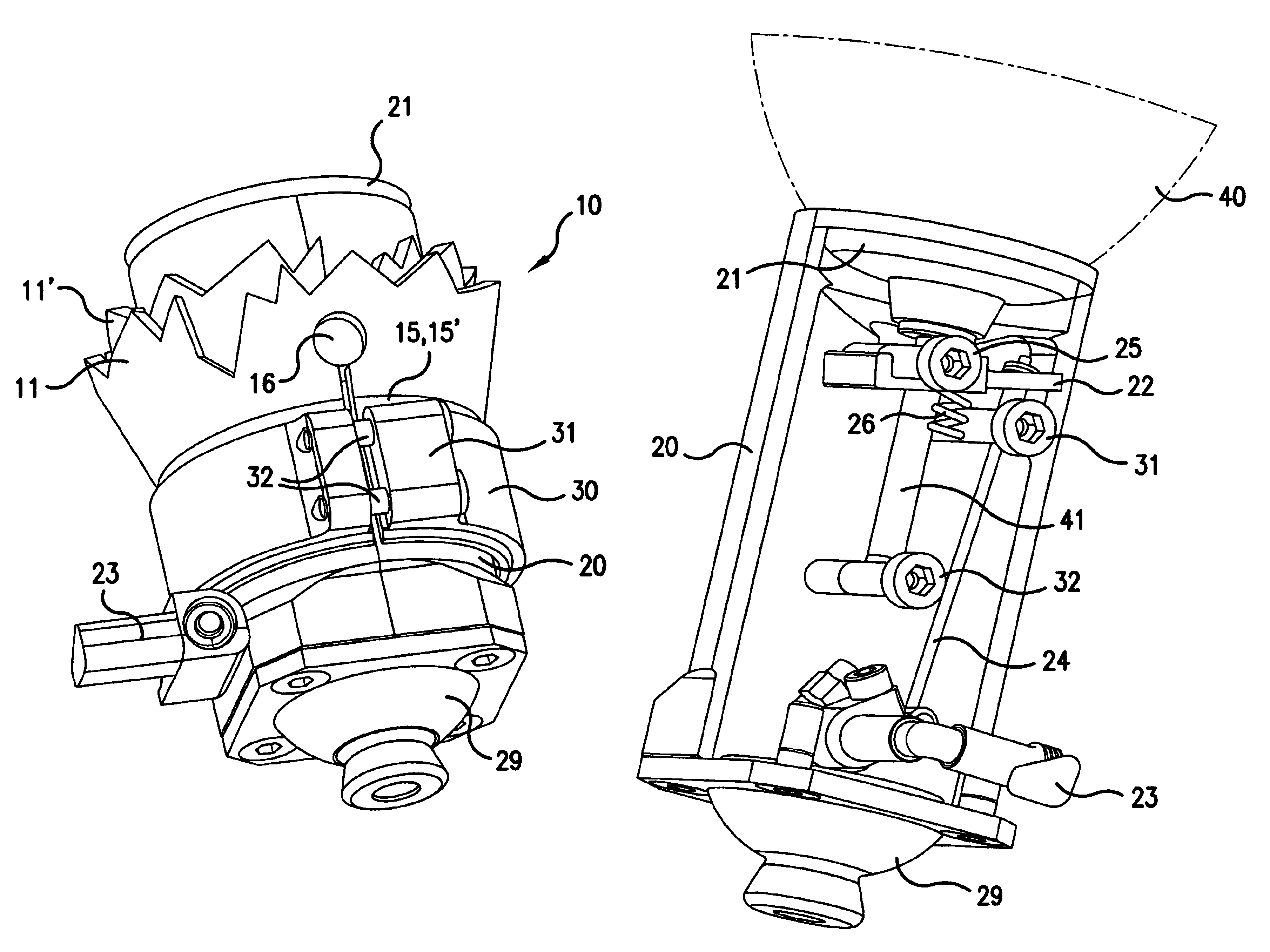
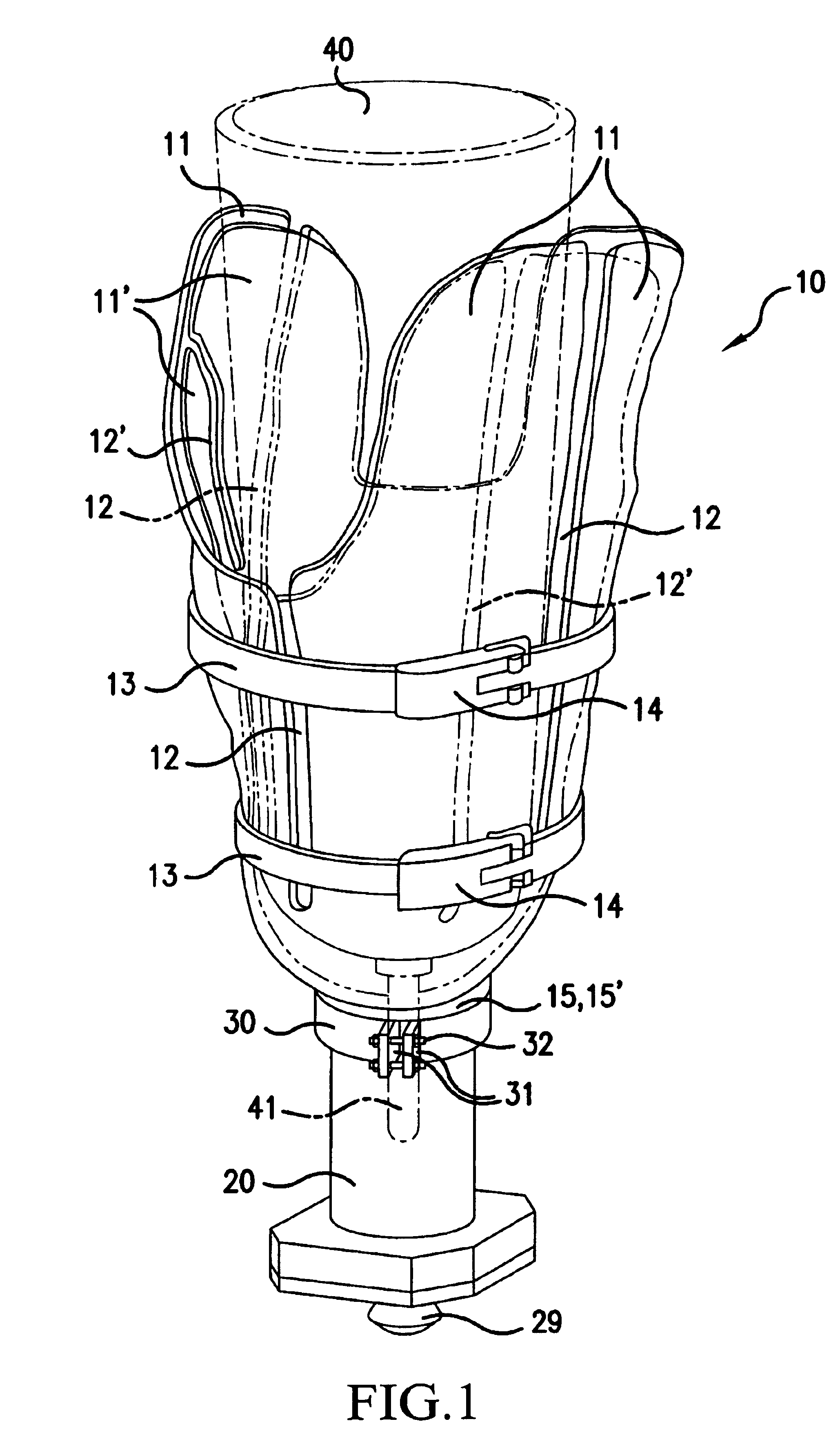
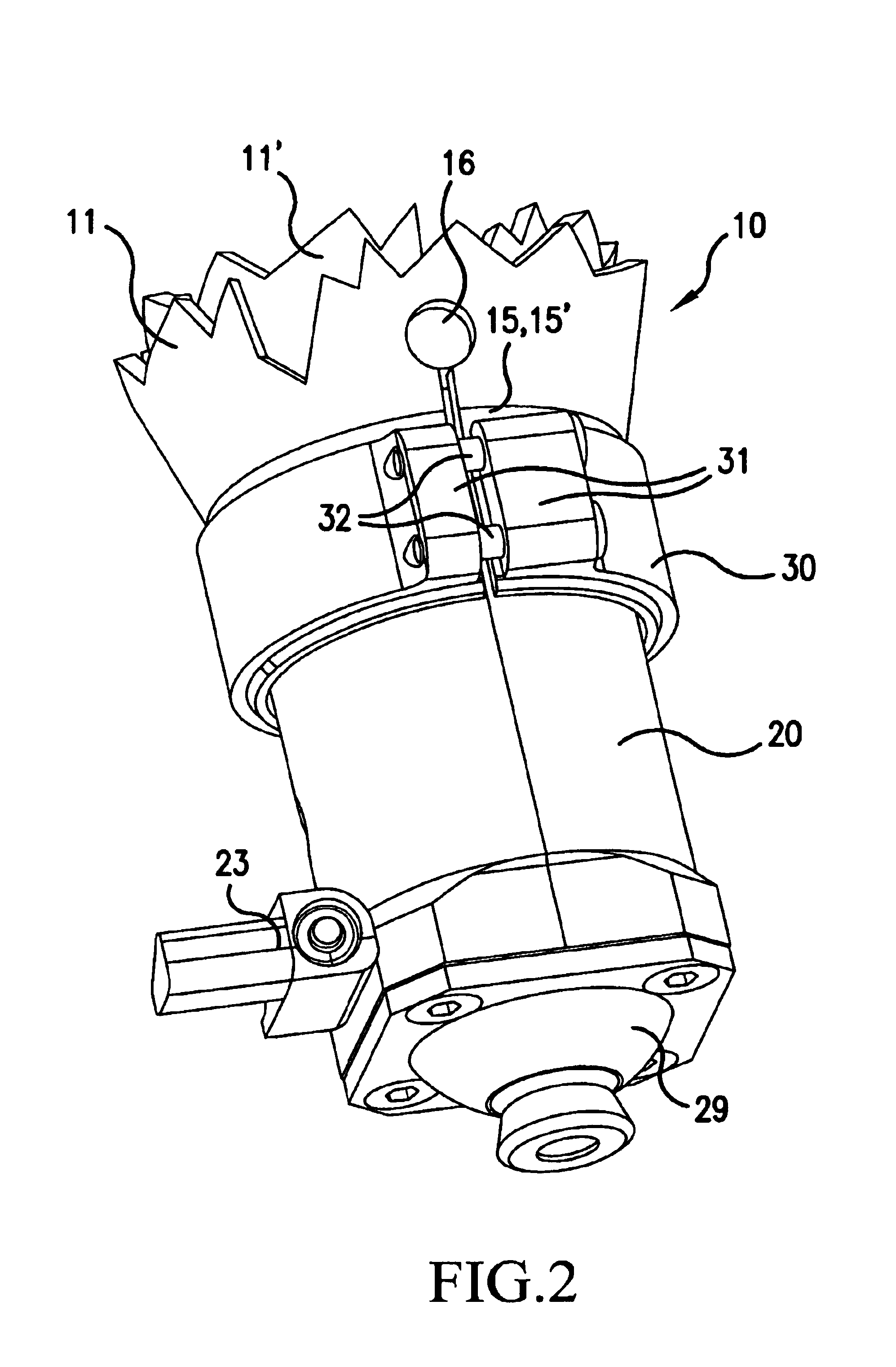
[0043]FIG. 1 is a perspective illustration of a prosthesis shaft 10, which is anatomically fitted to a limb stump (not shown), at the bottom of which, a coupling 29, e.g., a holding element, is mounted to which, if need be, an artificial limb, for example an arm or foot prosthesis, can be attached via an extension rod.

[0044]The prosthesis shaft 10 includes an outer shell 11 and an inner shell 11′. In the outer and inner shells 11, 11′, there are slits 12, 12′ extending essentially in an axial direction, which are staggered in relation to each other. In an ideal situation, the outer and inner shell 11, 11′ touch each other like the skins of an onion.

[0045]When the outer and inner shell 11, 11′ is made of a carbon fiber-reinforced plastic, thinner walls and thus reduced weight can be achieved. If the reinforced fibers extend mostly in an axial direction, the shells 11, 11′ are inflexible in a longitudinal direction, and flexible in a circumferential direction.

[0046]In order to be able...


PUM


Abstract

The invention relates to prostheses for amputated patients. The shaft of the prosthesis has an outer shell and a concentric inner shell. Both shells are provided with longitudinal slits which are staggered in relation to each other and extend essentially in an axial direction. The diameter of the shaft of the prosthesis can be adjusted by tightening elements. An adaptor is fixed in the shaft of the prosthesis in such a way that the height of the adapter can be adjusted. A conical bearing surface for the stump of the limb is provided on the upper side of the adapter, a holding element for fixing an artificial limb is provided on the lower side of the same, and a coupling is provided inside the adapter for detachably fixing the coupling pin of a commercially available silicone liner.

Description

BACKGROUND OF THE INVENTION[0001]1. Field of the Invention[0002]The present invention relates to prostheses including a silicone liner with a coupling pin, a prosthesis shaft adapted to a limb stump, provided with longitudinal slits in portions thereof, the diameter being adjustable by tightening elements, and a holding device to connect artificial limbs with the shaft of the prosthesis.[0003]2. Description of the Background Art[0004]The purpose of prostheses is to replace, as best as possible, limbs that were lost through an accident or illness. To temporarily attach prostheses, for example artificial hands or feet, to a limb stump, special prosthesis shafts are used, which must be anatomically fitted to the limb stump. The attachment is commonly achieved by a vacuum between the prosthesis shaft and the limb stump or between the limb stump and a silicone liner.[0005]Prosthesis shafts are made of metal, wood or cast resin. There are shafts of longitudinal or cross-oval shape, full-c...

Claims


Application Information

Patent Timeline
Patent Type & Authority Patents(United States)
IPC IPC(8): A61F2/80A61F2/50A61F2/78A61F2/00A61F2/60A61F2/76A61F2/54
CPCA61F2/78A61F2/80A61F2/54A61F2/60A61F2/76A61F2/7812A61F2002/30276A61F2002/30334A61F2002/30354A61F2002/30401A61F2002/30464A61F2002/30492A61F2002/30505A61F2002/30509A61F2002/30517A61F2002/30522A61F2002/5003A61F2002/502A61F2002/5026A61F2002/5027A61F2002/503A61F2002/5055A61F2002/5075A61F2002/5081A61F2002/5083A61F2002/7856A61F2002/7862A61F2002/7881A61F2002/7893A61F2220/0025A61F2220/0033A61F2220/0075A61F2230/0086A61F2002/30462A61F2002/30507
Inventor CARSTENS, JOHANNES
Owner LUISA CERANO
Why Eureka
Try Eureka