Device for spraying water

a technology for thermal power plants and water tanks, which is applied in the direction of nuclear elements, metal/metal-oxide/metal-hydroxide catalysts, and the nature of treatment water, etc. it can solve the problems of increasing the maintenance interval of the water-steam circuit, bringing cost advantages, and increasing the life of the components arranged in it, so as to increase the operational safety of the power plant and reduce the cost. , the effect of low expenditur

Inactive Publication Date: 2007-07-31
BALCKE DURR AG
View PDF6 Cites 0 Cited by
  • Summary
  • Abstract
  • Description
  • Claims
  • Application Information

AI Technical Summary

Benefits of technology

[0017]Finally another advantage of the invention is that even existing spraying devices can be refitted with a catalyst with relatively low expenditure. Thus the advantages of the invention can also be cost-efficiently applied to already existing plants.
[0018]The first preferred design form of the invention provides for a catalyst that is designed to convert hydrogen and oxygen gas to water. Such a design of the catalyst is particularly of great advantage when the feedwater circulates in a nuclear power plant of the boiling-water reactor type. The mixture of hydrogen and oxygen formed by the effect of the radioactive radiation on the water is then converted safely to water by means of the catalyst that is arranged in the spraying device. In this way the highly inflammable hydrogen gas and also the highly explosive detonating gas mixture are withdrawn from the thermal circuit, thus increasing the operational safety of the power plant. Numerous metals and metalorganic compounds are known for use as catalysts for the conversion of the photolysis gases to water.
[0019]It is therefore particularly useful if the catalyst contains at least precious metal. Basically all precious metals known from prior art conversion of gases can be used. However, particularly preferred metals are those of the 8. subgroup of the Periodic Table of the Elements (Ni, Pd, Pt), particularly platinum. These metals can convert numerous gases catalytically and are also outstandingly suitable for the catalytic combustion of hydrogen and oxygen to water. In addition to one precious metal, even several precious metals for example, nickel and platinum can be present in the catalyst. The precious metals can be present in the catalyst either in parallel or also in the form of an alloy.
[0020]Another preferred design form of the invention provides a catalyst that is designed as bulk material. Such a catalyst can be manufactured easily and is characterized by a long life-span due to its robustness. The conversion of the gases contained in the water can thus take place reliably over a longer period of time.
[0021]It can also be useful if the catalyst is designed as a substrate with a catalytically active coating. The advantage of such a design form is that only the coating has to consist of a catalytically active material such as a precious metal, while the substrate can be manufactured from a considerably lower priced material. Materials known to prior art are used as substrates. These include metal oxides particularly γ-Al2O3, metal alloys, ceramics and refractory plastics. In this manner a cost-effective catalyst can be produced that ensures a reliable removal of the gases contained in the water.
[0022]In addition it can be advantageous if the catalyst has a sheet metal structure. In the following, the term sheet metal means a body whose thickness is small to its surface measurement. The sheet metal can be designed as a catalytically active bulk material or as a substrate for a catalytically active coating. Basically all structures known to prior art are applicable for the structure of the sheet metal. Thus the structure can be a regular or irregular sequence of elevations and depressions for example in the form of a wavy pattern or a jagged pattern. Even a relatively rough-textured surface, for example a dendritic coating, is possible while preparing a large active surface. In addition the sheet structure can form a multi-layer body, which further increases the catalytically active surface.

Problems solved by technology

By the removal of the gases from the thermal circuit, the lifespan of the components arranged in it is clearly increased since corrosion, by oxygen for example, is no longer possible.
Thus even the maintenance interval for the water-steam circuit also increases, thus bringing about cost advantages.

Method used


Image

  • Device for spraying water
  • Device for spraying water
  • Device for spraying water

Examples


Embodiment Construction

.

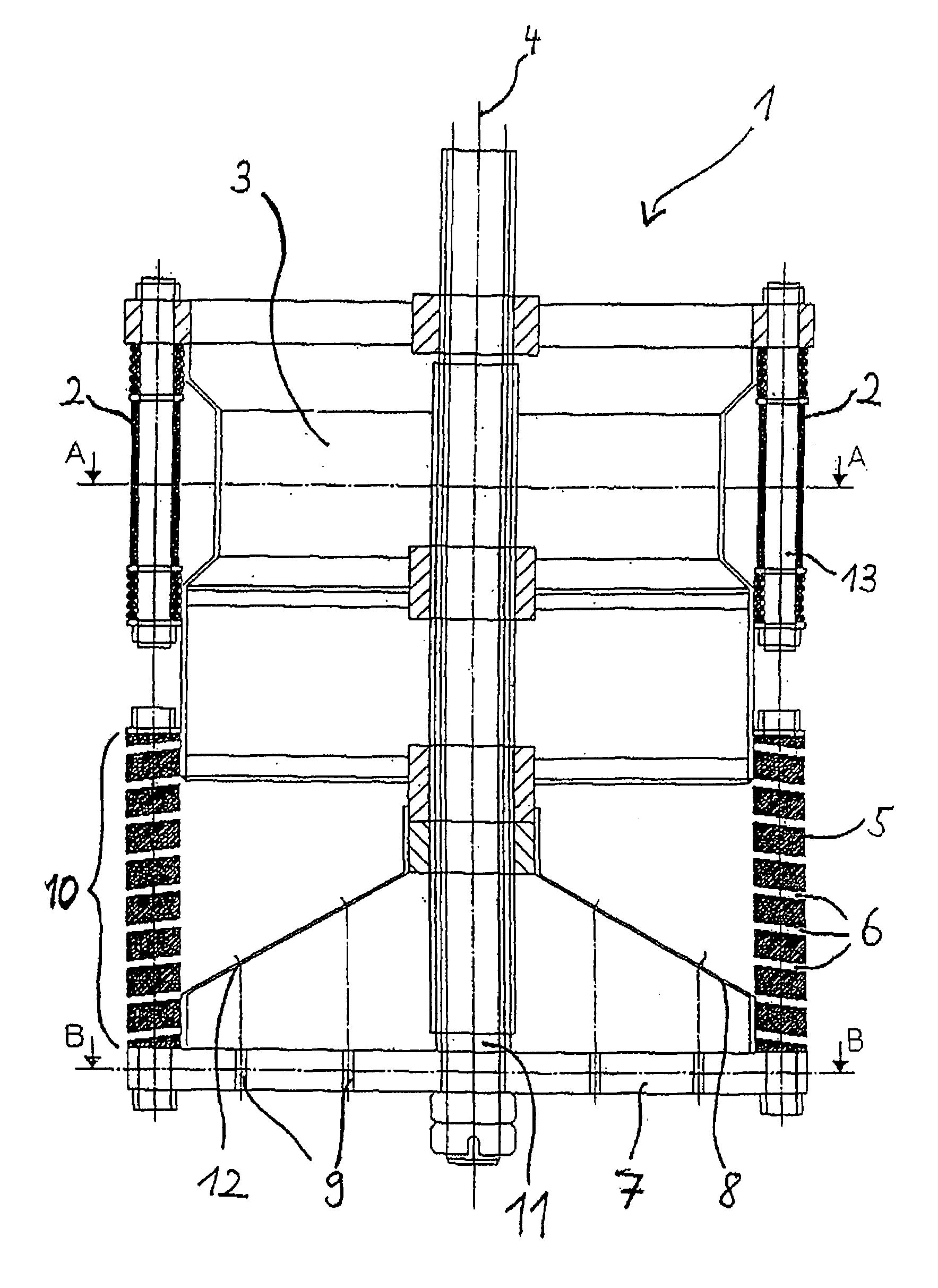
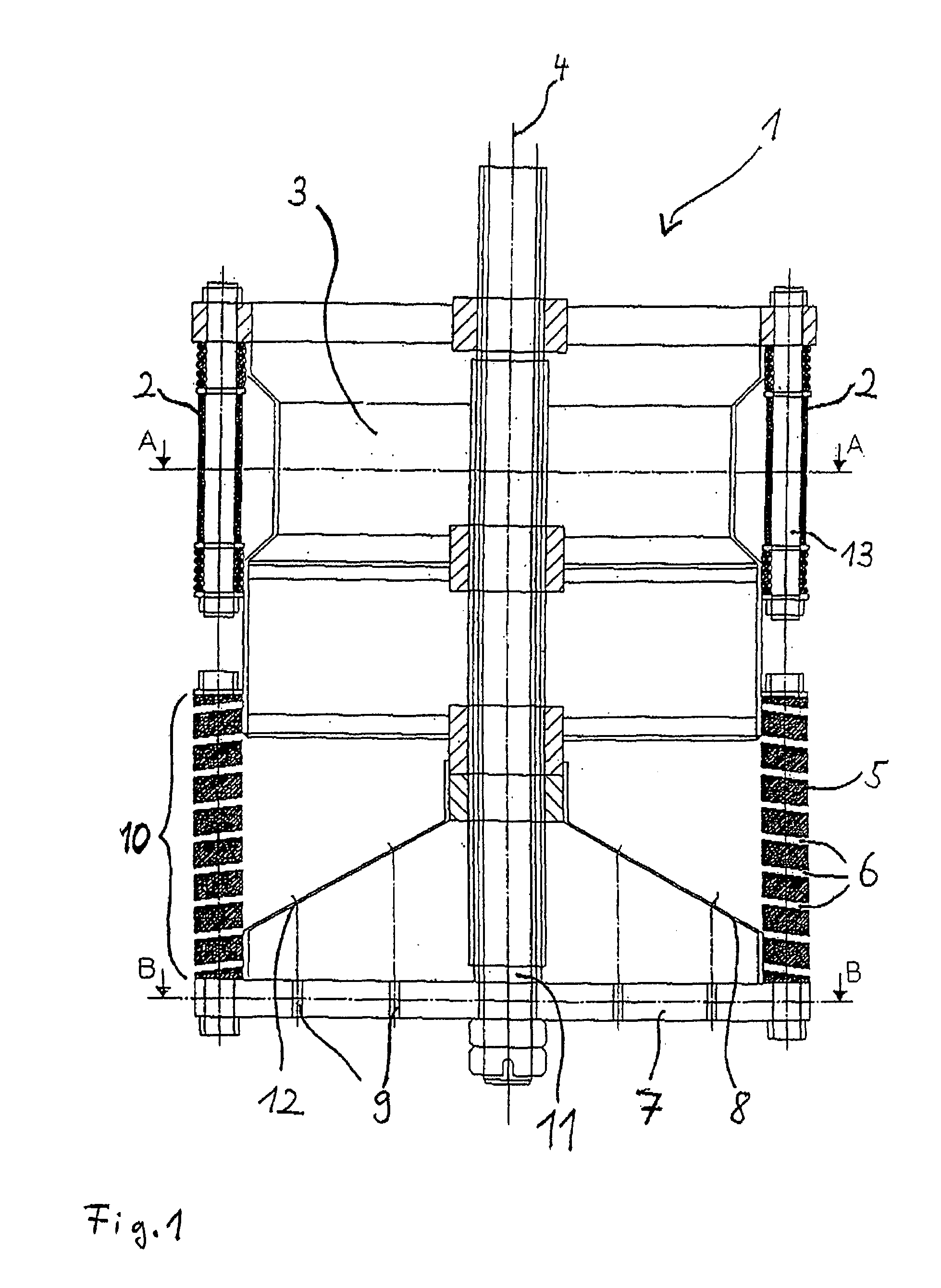
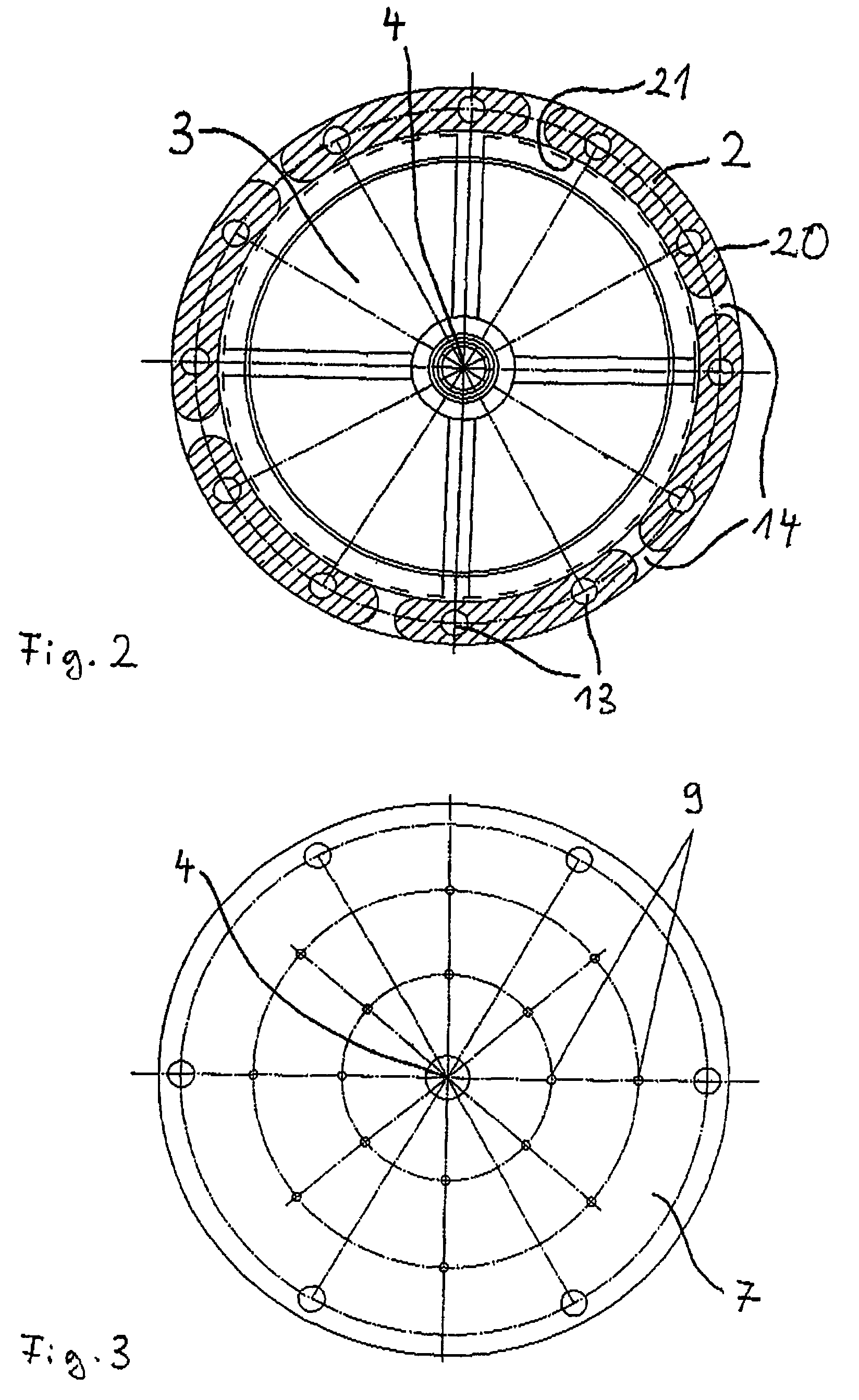
[0040]FIG. 1 illustrates a spraying device 1 with which the water to be degasified in a feedwater tank of a thermal power plant sprays and with which the gas discharged from the water is converted by a catalyst. The spraying device 1 is orientated in accordance with FIG. 1 in the feedwater tank that is not illustrated, i.e. the water is sprayed by a spray area 10 that is arranged in the lower area of the spraying device 1 while the conversion of the gases takes place on the catalyst that is arranged in an upper area of the spraying device 1.

[0041]The spraying device 1 has a cylinder symmetry wherein the axial direction (longitudinal direction) is defined by an axis 4. The spray area 10 is provided for spraying the water to be degasified. This spray area 10 has a spray spring 5 in the covering area 30 of the spraying device 1. The spray spring 5 has spring slots 6 as spray openings.

[0042]For converting the gas discharged from the sprayed water the spraying device 1 in accordance wit...


PUM

PropertyMeasurementUnit
areaaaaaaaaaaa
tensionaaaaaaaaaa
spray areasaaaaaaaaaa

Abstract

The invention concerns a device for spraying water in a feedwater tank of a thermal power plant. Because the spraying device comprises a catalyst for the conversion of the gases contained in the water, the gases released from the water during the spray degasification can be removed easily, reliably and completely. Thus, the degree of efficiency of the thermal circuit of the power plant and the lifespan of the components arranged in the circuit are increased.

Description

CROSS REFERENCE TO RELATED APPLICATIONS[0001]This application claims priority to European Patent Application Serial No. 04002728.6, filed Feb. 6, 2005, titled DEVICE FOR SPRAYING WATER, the disclosure of which is incorporated by reference in its entirety.FIELD OF THE INVENTION.[0002]The invention concerns a device for spraying water in a feedwater tank of a thermal power plant.BACKGROUND OF THE INVENTION.[0003]It is known that thermal power plants have a water-steam circuit (thermal circuit) in which a feedwater tank is arranged among other things. The feedwater tank is used for storing and reconditioning the water that is circulating in the thermal circuit. The degasification of the water is particularly important during the reconditioning process.[0004]In all thermal power plants a most complete degasification possible of the feedwater is indispensable for reliable and safe operation and also for achieving the highest efficiency of the plant. The gases to be removed include partic...

Claims


Application Information

Patent Timeline
Patent Type & Authority Patents(United States)
IPC IPC(8): B01J8/02B01J15/00B01D19/00B01J23/40B01J35/04B05B1/14B05B1/30B05B1/32C02F1/20C02F1/72F22D1/50
CPCC02F1/20G21C19/307B05B1/323C02F1/725C02F2103/023G21Y2002/103G21Y2004/20G21Y2004/40B01J23/40B01J35/04B05B1/3006Y02E30/30
Inventor GROBELNY, GUNTERKECK, ROBERT-JOACHIM
Owner BALCKE DURR AG
Why Eureka
Try Eureka