Method and apparatus of providing an optical fiber along a power supply line
What is AI technical title?
AI technical title is built by PatSnap AI team. It summarizes the technical point description of the patent document.
a technology of optical fiber and power supply line, which is applied in the field of oilfield operations, can solve the problems of not providing continuous information about the condition of the wellbore or the surrounding formation, high cost, and inapplicability, and achieves the effect of high temperatur
Inactive Publication Date: 2005-09-13
SENSOR HIGHWAY LTD
View PDF15 Cites 22 Cited by
Summary
Abstract
Description
Claims
Application Information
AI Technical Summary
This helps you quickly interpret patents by identifying the three key elements:
Problems solved by technology
Method used
Benefits of technology
Benefits of technology
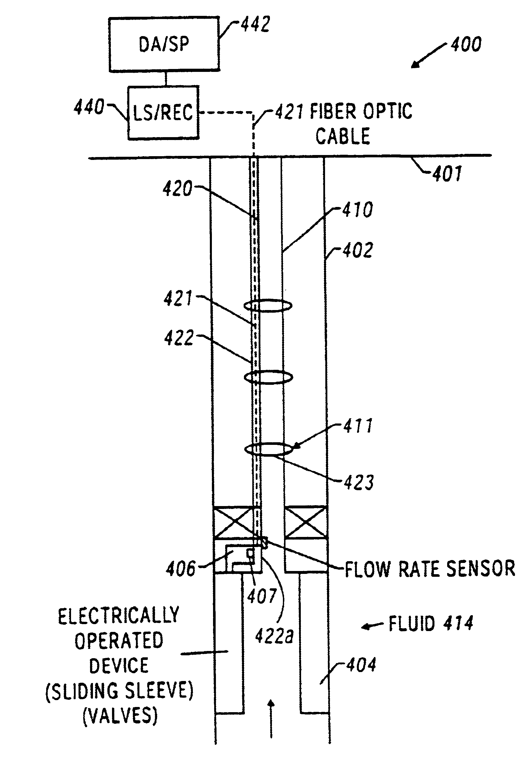
[0017]In an application to control of injection wells, the invention provides significantly more information to well operators thus enhancing oil recovery to a degree not heretofore known. This is accomplished by providing real time information about the formation itself and the flood front by providing permanent downhole sensors capable of sensing changes in the swept and unswept formation and / or the progression of the flood front. Preferably a plurality of sensors would be employed to provide information about discrete portions of strata surrounding the injection well. This provides a more detailed data set regarding the well(s) and surrounding conditions. The sensors are, preferably, connected to a processor either downhole or at the surface for processing of information. Moreover, in a preferred embodiment the sensors are connected to computer processors which are also connected to sensors in a production well (which are similar to those disclosed in U.S. Pat. No. 5,597,042 which is fully incorporated herein by reference) to allow the production well to “talk” directly to the related injection well(s) to provide an extremely efficient real time operation. Sensors employed will be to sense temperature, pressure, flow rate, electrical and acoustic conductivity, density and to detect various light transmission and reflection phenomena. All of these sensor types are available commercially in various ranges and sensitivities which are selectable by one of ordinary skill in the art depending upon particular conditions known to exist in a particular well operation. Specific pressure measurements will also include pressure(s) at the exit valve(s) down the injection well and at the pump which may be located downhole or at the surface. Measuring said pressure at key locations such as at the outlet, upstream of the valve(s) near the pump will provide on about the speed, volume, direction, etc. at / in which the waterflood front (or other fluid) is moving. Large differences in the pressure from higher to lower over a short period of time could indicate a breakthrough. Conversely, pressure from lower to higher over short periods of time could indicate that the flood front had hit a barrier. These conditions are, of course, familiar to one of skill in the art but heretofore far less would have been known since no workable system for measuring the parameters existed. Therefore the present invention since it increases knowledge, increases productivity.
[0019]The distributed sensors of this invention find particular utility in the monitoring and control of various chemicals which are injected to the well. Such chemicals are needed downhole to address a large number of known problems such as for scale inhibition and various pretreatment of the fluid being produced. In accordance with the present invention, a chemical injection monitoring and control system includes the placement of one or more sensors downhole in the producing zone for measuring the chemical properties of the produced fluid as well as for measuring other downhole parameters of interest. These sensors are preferably fiber optic based and are formed from a sol gel matrix and provide a high temperature, reliable and relatively inexpensive indicator of the desired chemical parameter. The downhole chemical sensors may be associated with a network of distributed fiber optic sensors positioned along the wellbore for measuring pressure, temperature and / or flow. Surface and / or downhole controllers receive input from the several downhole sensors, and in response thereto, control the injection of chemicals into the borehole.
Problems solved by technology
The above described methods are very expensive.
The wire methods are utilized at relatively large time intervals, thereby not providing continuous information about the wellbore condition or that of the surrounding formations.
To obtain such measurements from the entire useful segments of each wellbore, which may have multi-lateral wellbores, requires using a large number of sensors, which requires a large amount of power, data acquisition equipment and relatively large space in the wellbore: this may be impractical or prohibitively expensive.
Because of the harsh operating conditions downhole, electrical cables are subject to degradation.
In addition, due to long electrical path lengths for downhole devices, cable resistance becomes significant unless large cables are used.
This is difficult to do within the limited space available in production strings.
In addition, due to the high resistance, power requirements also became large.
As is well known to the are, one of the most common drawbacks of employing the method above noted with respect to injection wells is an occurrence commonly identified as “breakthrough”.
Moreover, other geologic conditions such as faults and unconformities also affect the in-situ sweep efficiency.
However, it can be difficult to monitor and control such chemical injection in real time.
However, it can be difficult to monitor and control such treatment in real time.
Method used
Image
Click on the blue label to locate the original text in one second.
Reading with bidirectional positioning of images and text.
Examples
Embodiment Construction
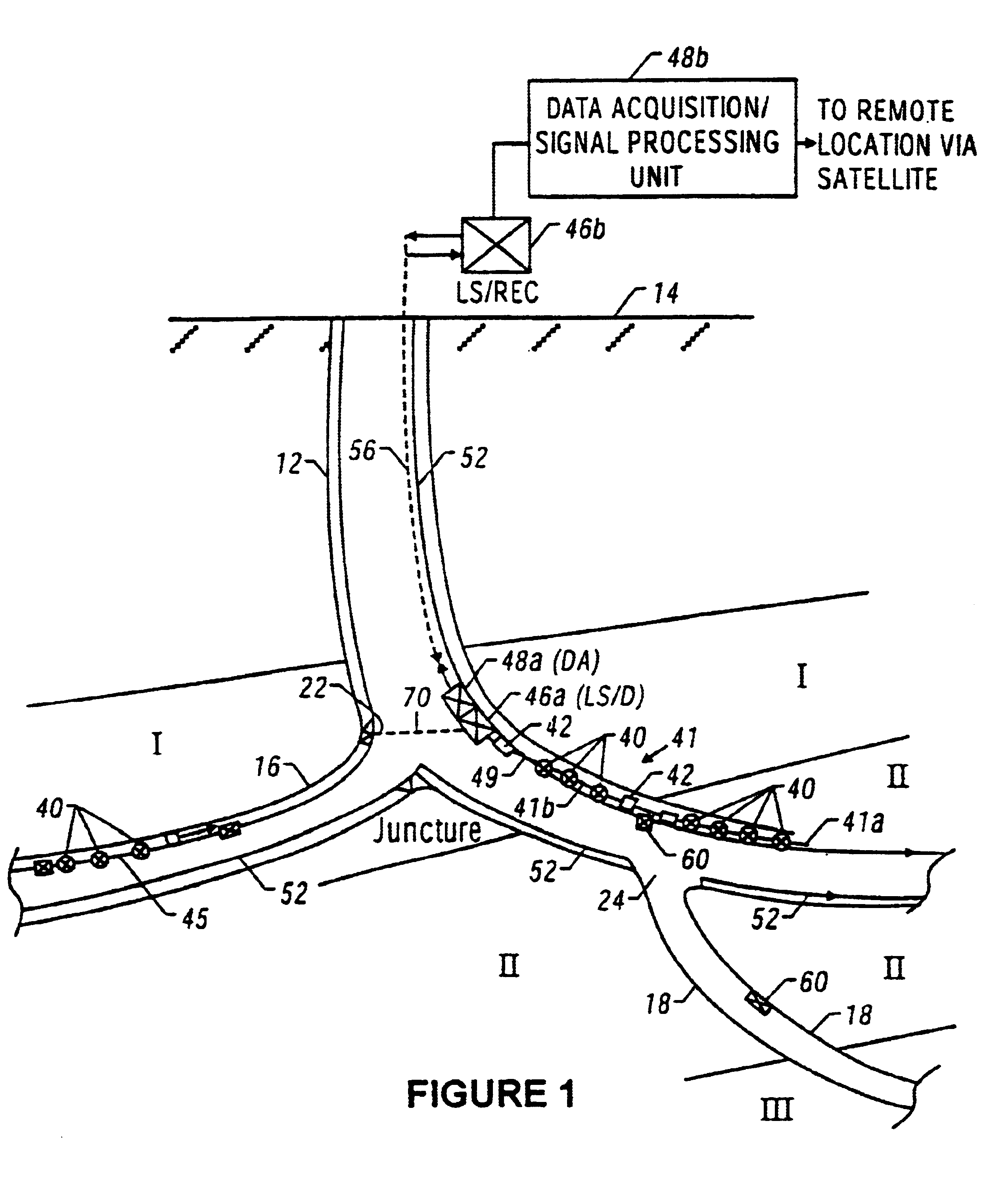
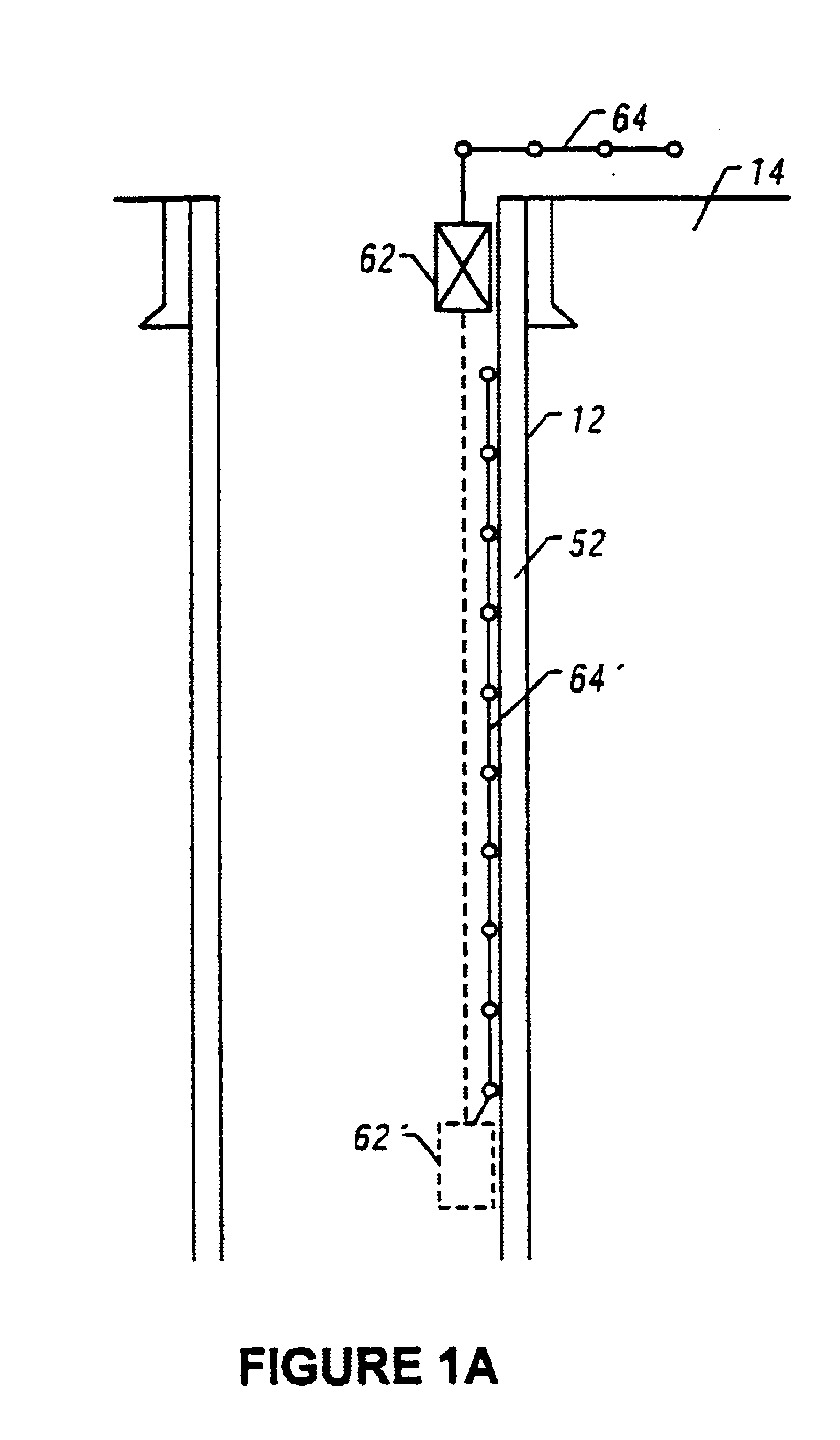
[0042]The various concepts of the present invention will be described in reference to FIGS. 1-17, which show a schematic illustration of wellbores utilizing fiber optic-based sensor and operating devices.
[0043]FIG. 1 shows an exemplary main or primary wellbore 12 formed from the earth surface 14 and lateral wellbores 16 and 18 formed from the main wellbore 18. For the purpose of explanation, and not as any limitation, the main wellbore 18 is partially formed in a producing formation or pay zone I and partially in a non-producing formation or dry formation II. The lateral wellbore 16 extends from the main wellbore at a juncture 22 into the producing formation I, while the lateral wellbore 16 extents from the main wellbore 12 at juncture 24 into a second producing formation III. For the purposes of this illustration only, the wellbores herein are shown as being drilled on land; however, this invention is equally applicable to offshore wellbores. It should be noted that all wellbore co...
PUM
Property
Measurement
Unit
length
aaaaa
aaaaa
electrical power
aaaaa
aaaaa
temperature
aaaaa
aaaaa
Abstract
This invention provides a method for controlling production operations using fiber optic devices. An optical fiber carrying fiber-optic sensors is deployed downhole to provide information about downhole conditions. Parameters related to the chemicals being used for surface treatments are measured in real time and on-line, and these measured parameters are used to control the dosage of chemicals into the surface treatment system. The information is also used to control downhole devices that may be a packer, choke, sliding sleeve, perforation device, flow control valve, completion device, an anchor or any other device. Provision is also made for control of secondary recovery operations online using the downhole sensors to monitor the reservoir conditions. The present invention also provides a method of generating motive power in a wellbore utilizing optical energy. This can be done directly or indirectly, e.g., by first producing electrical energy that is then converted to another form of energy.
Description
CROSS REFERENCE TO RELATED APPLICATIONS[0001]This is a divisional of U.S. Ser. No. 10 / 336,154, filed Jan. 3, 2003, now U.S. Pat. No. 6,828,547, which is a divisional of U.S. Ser. No. 09 / 778,696, filed Feb. 6, 2001, now U.S. Pat. No. 6,531,694, which is a divisional of U.S. Ser. No. 09 / 071,764, filed May 1, 1998 (now U.S. Pat. No. 6,281,489), which claims the benefit under 35 U.S.C. § 119(e) of Provisional U.S. Patent Applications Ser. Nos. 60 / 045,354 filed on May 2, 1997; 60 / 048,989 filed on Jun. 9, 1997; 60 / 052,042 filed on Jul. 9, 1997; 60 / 062,953 filed on Oct. 10, 1997; 60 / 073,425 filed on Feb. 2, 1998; and 60 / 079,446 filed on Mar. 26, 1998. Each of the reference applications is hereby incorporated by reference.BACKGROUND OF THE INVENTION[0002]1. Field of the Invention[0003]This invention relates generally to oilfield operations and more particularly to the downhole apparatus utilizing fiber optic sensors and use of same in monitoring the condition of downhole equipment, monitori...
Claims
Application Information
Patent Timeline
Application Date:The date an application was filed.
Publication Date:The date a patent or application was officially published.
First Publication Date:The earliest publication date of a patent with the same application number.
Issue Date:Publication date of the patent grant document.
PCT Entry Date:The Entry date of PCT National Phase.
Estimated Expiry Date:The statutory expiry date of a patent right according to the Patent Law, and it is the longest term of protection that the patent right can achieve without the termination of the patent right due to other reasons(Term extension factor has been taken into account ).
Invalid Date:Actual expiry date is based on effective date or publication date of legal transaction data of invalid patent.

