Tubular linear synchronous motor control for elevator doors

Inactive Publication Date: 2005-09-13
OTIS ELEVATOR CO
View PDF18 Cites 10 Cited by
  • Summary
  • Abstract
  • Description
  • Claims
  • Application Information

AI Technical Summary

Benefits of technology

[0009]In accordance with the present invention, an apparatus for effecting non-contact linear door displacement comprises a tubular motor comprising a stator formed from a plurality of magnets arranged along a linear axis, and at least one thrust block each comprising at least one electrically conductive coil encircling the stator at a distance sufficient to facilitate electromagnetic interaction between the plurality of coils and the stator, at least one door attached to at least one of the plurality of thrust blocks via a hanger and the at least one door capable of a movement in the direction of the linear axis, a rolling means to enable movement of the hanger in the direction of the linear axis, and a control mechanism for sensing the position of each of the at least one door and issuing an electrical control signal to each of the plurality of thrust blocks so as to affect the movement of the at least one door.
[0010]In accordance with the present invention, an apparatus for controlling tubular linear synchronous motor doors comprises a master-slave control circuit capable of measuring an actual master position of a master door having a master status and an actual slave position of a slave door having a slave status, a position control profile accessible to the master-slave control circuit, component capable of comparing the measured actual master position to the position control profile to compute a master position error, component capable of calculating a master electrical force from the computed master position error, component capable of transmitting the calculated master electrical force to the master door, component capable of providing as an input the actual master position to the slave door, component capable of measuring an a

Problems solved by technology

Such assemblages are often found in the context of elevators wherein their arrangement give

Method used


Image

  • Tubular linear synchronous motor control for elevator doors
  • Tubular linear synchronous motor control for elevator doors
  • Tubular linear synchronous motor control for elevator doors

Examples


Embodiment Construction

)

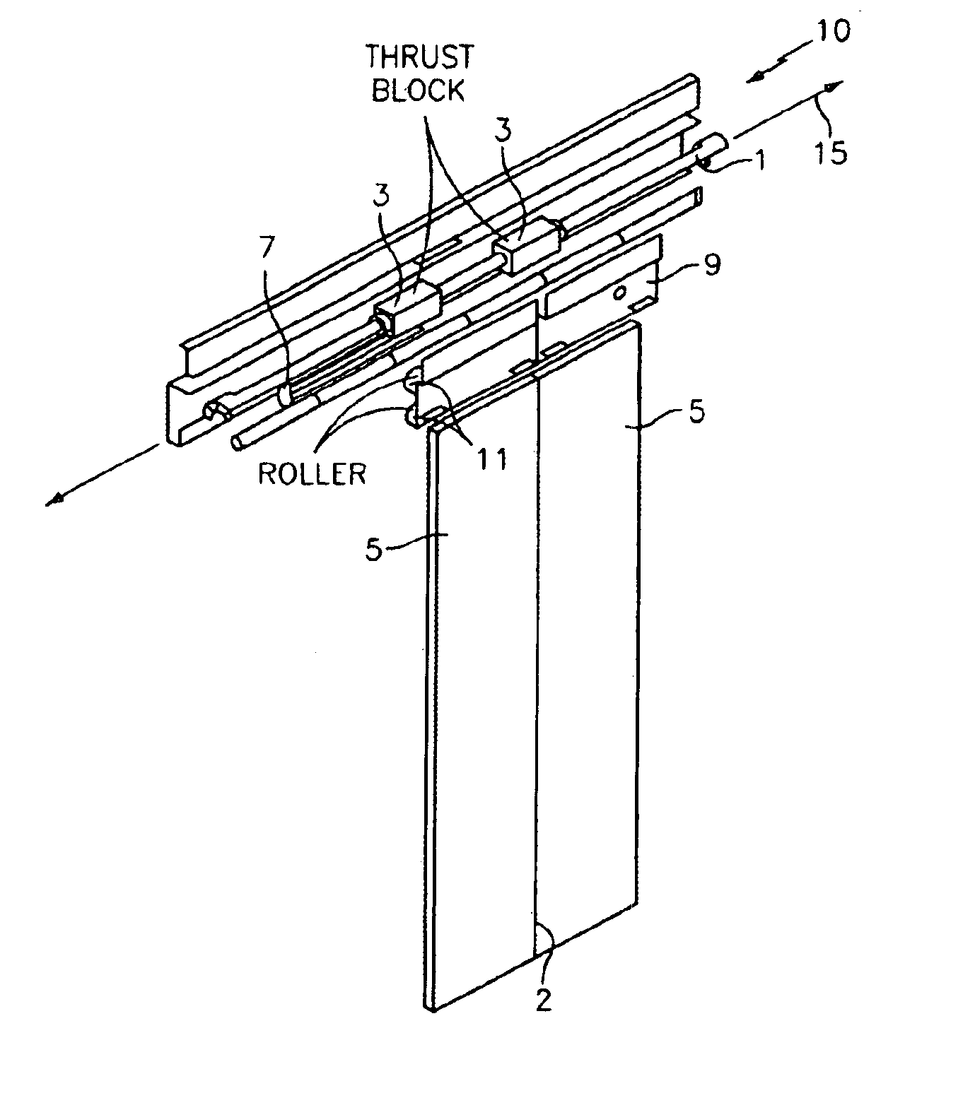
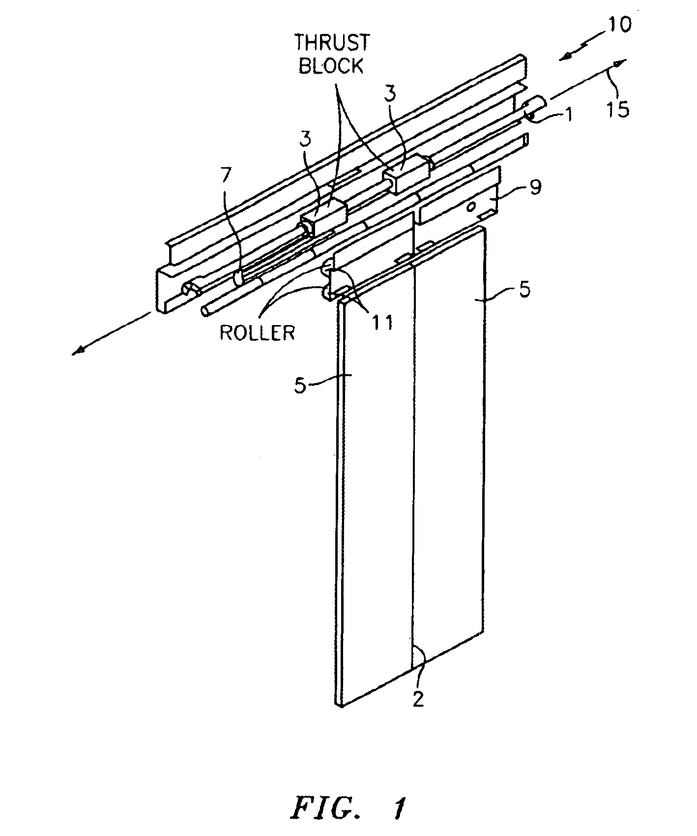
[0018]With reference to FIG. 1, there are illustrated the primary elements of the door apparatus of the present invention. While illustrated with respect to embodiments comprising configurations of elevator doors, the present invention is not so limited. Rather, the present invention is drawn broadly to include any moving or stationary platform upon which the non-contact, linear door displacement apparatus of the present invention may be mounted. In addition, while there is illustrated a preferred embodiment of the present invention in which two doors are displaced along a linear axis in opposing directions about a center line 2, the present invention may be likewise utilized to move a single door or a door within a door such as in a telescoping configuration.

[0019]Motive force is applied to doors 5, through the use of a tubular linear synchronous motor (TLSM). In a preferred embodiment, a TLSM is comprised of a stator 1 and at least one thrust block 3 comprised of a plurality of c...


PUM


Abstract

An apparatus for effecting non-contact linear door displacement comprising a tubular motor formed of a stator (1) formed from a plurality of magnets (21) arranged along a linear axis (15), and at least one thrust block (3) each formed of at least one electrically conductive coil encircling the stator (1) at a distance sufficient to facilitate electro-mechanical interaction between the plurality of coils and the stator (1), at least one door (5) attached to at least one of the plurality of thrust blocks (3) via a hanger (9) and the at least one door (5) capable of a movement in the direction of the linear axis (15), a rolling component (11) to enable movement of the hanger (9) in the direction of the linear axis (15), and a control mechanism (70) for sensing the position of each of the at least one door (5) and issuing an electrical control signal to each of the plurality of thrust blocks (3) so as to affect the movement of the at least one door (5).

Description

BACKGROUND OF THE INVENTION[0001](1) Field of the Invention[0002]The present invention relates to tubular linear synchronous motor (TLSM) door assembly for providing motive force to a door or doors. More specifically, this invention relates to an apparatus incorporating a TLSM with control circuitry to provide sensor-less control of an elevator door configuration.[0003](2) Description of Related Art[0004]Use of motor assemblages and associated control mechanisms for accomplishing the automated opening and closing of doors is well known. Such assemblages are often found in the context of elevators wherein their arrangement gives rise to concerns regarding efficiency, noise, lifetime, and maintenance of the assemblage.[0005]Common door control implementations require a sensing apparatus, such as an optical sensor, for determining the precise location of a door or doors at all times. While optical sensors can be used to determine the position of a door to within fractions of a millimet...

Claims


Application Information

Patent Timeline
IPC IPC(8): B66B13/02B66B13/14B66B13/08E05F15/60H02P25/06
CPCB66B13/08B66B13/143
Inventor MORRIS, NIGEL BRUCEDURAND, CHRISTOPHEGOSTERISLI, LEVENTHE, THOMASREBILLARD, PASCALZAHARIA, VLAD
Owner OTIS ELEVATOR CO
Why Eureka
Try Eureka