Submersible power plant having multiple turbines

a technology of power plant and turbine, which is applied in the direction of motors, tethered aircraft, underwater equipment, etc., can solve the problems of increasing the cost of the submerged plant, and achieve the effects of increasing the ruggedness of the power plant, reducing pitch instability, and relatively complex design and manufacturing

Inactive Publication Date: 2016-04-28
MINESTO
View PDF9 Cites 11 Cited by
  • Summary
  • Abstract
  • Description
  • Claims
  • Application Information

AI Technical Summary

Benefits of technology

[0008]Different counter-torques applied to the respective first, second and third turbines causes a translational and/or rotational force to be exerted on the vehicle by means of that different fluid dynamic pressures are exerted on said first turbine, the second turbine and the third turbine by the fluid, causing the vehicle to pitch and/or yaw. Different pressure can be exerted on one or more of the turbines. This effect removes the need for additional control surfaces such as a rudder. Removing a moving part such as a rudder together with servos controlling the rudder increases the ruggedness of the power plant. A submersible power plant may alternatively use front and rear struts to give the tether an attachment point far below the wing. This reduces pitch instability and the influence of hydrostatic unbalance. This is a system involving several parts and a number of couplings and is therefore relatively complex to design and manufacture and which may increase the cost of the submersible plant.
[0009]In the present invention struts are no longer necessary which further reduces the complexity of the power plant. The present invention also makes it possible to move the tether coupling into the wing or into a coupling arrangement mounted close to the wing.
[0010]Further, by using at least three turbines, each turbine can be made smaller than when only one turbine is used. This leads to that controlling each turbine and generator combination is made easier due to the reduced power of each turbine and generator. This means that the power control electronics are easier to design. Having smaller turbines also simplifies cooling of the generators and their power control electronics and

Problems solved by technology

This is a system involving several parts and a number of couplings and is therefore relativel

Method used


Image

  • Submersible power plant having multiple turbines
  • Submersible power plant having multiple turbines
  • Submersible power plant having multiple turbines

Examples


Embodiment Construction

[0038]In the drawings, like features have the same reference numbers.

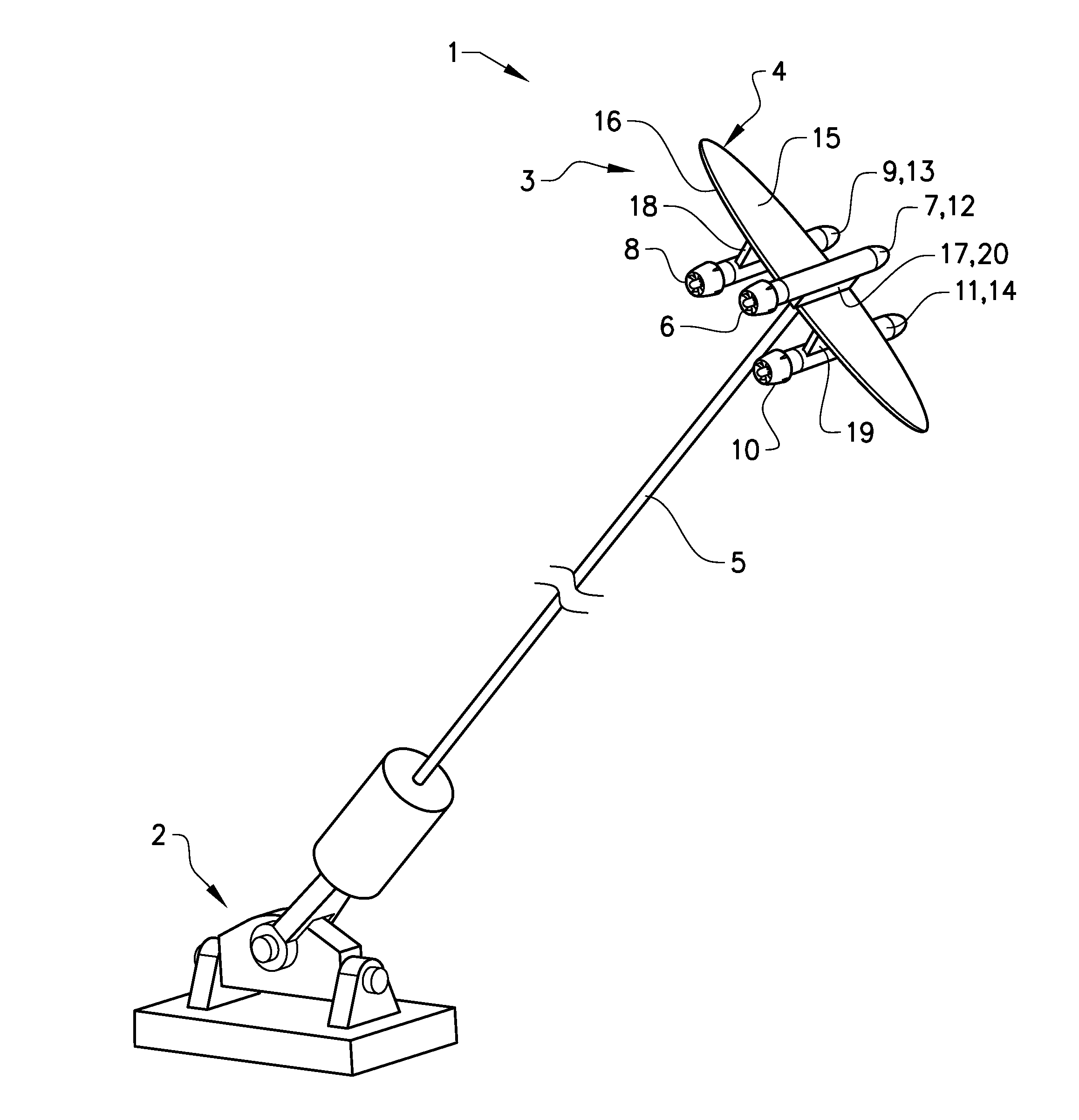
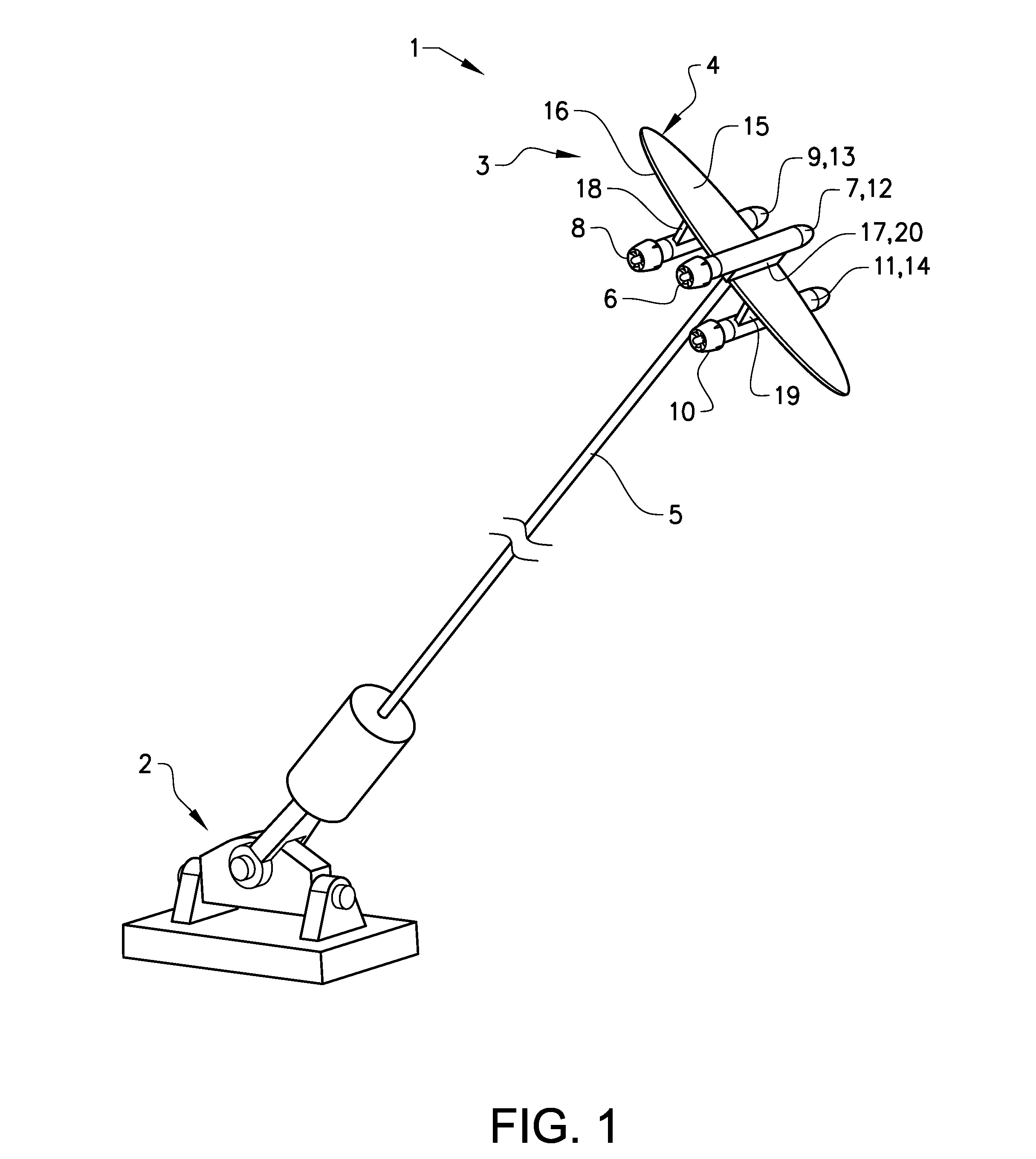
[0039]FIG. 1 schematically illustrates a submersible power plant 1 according to the invention. The submersible power plant 1 comprises a structure 2 and a vehicle 3 comprising at least one wing 4. The vehicle 3 is secured to the structure 2, which is located on a surface at the bottom of a body of water, by means of at least one tether 5. The vehicle 3 is arranged to move in a predetermined trajectory by means of a fluid stream passing the wing 4. The tether 5 is arranged to transport power to or from the power plant 1. The submersible power plant 1 comprises at least a first turbine 6, connected to a first nacelle 7, a second turbine 8 connected to a second nacelle 9 and a third turbine 10 connected to a third nacelle 11. The first nacelle 7, second nacelle 9 and third nacelle 11 comprises a first generator 12, a second generator 13 and third generator 14 respectively where each generator 12, 1314 is attached to i...


PUM


Abstract

A submersible power plant comprises a structure and a vehicle with a wing. The vehicle is arranged to be secured to the structure by ae tether. The vehicle is arranged to move in a predetermined trajectory by a fluid stream passing the wing. The submersible power plant comprises at least a first turbine, a second turbine and a third turbine being arranged to be attached to the wing of the vehicle. The first turbine is connected to a first generator, the second turbine is connected to a second generator, and the third turbine is connected to a third generator. At least one turbine is attached to the vehicle on a top surface of the wing, and at least one turbine is attached to a bottom surface of the wing. The generators are arranged to be able to produce different fluid dynamics pressures exerted on the respective turbines by torque control.

Description

CROSS REFERENCE TO RELATED APPLICATIONS[0001]This application is a U.S. National Stage patent application of PCT / SE2013 / 050625, filed on May 30, 2013, the entire contents of which are incorporated herein by reference.FIELD OF THE INVENTION[0002]The invention relates to a submersible power plant for generating electrical power. The power plant comprises a structure and a vehicle comprising at least one wing. The vehicle is arranged to be secured to the structure by means of at least one tether. The vehicle is arranged to move in a predetermined trajectory by means of a fluid stream passing the wing. The power plant comprises at least a first turbine, a second turbine and a third turbine being arranged to be attached to the wing of the vehicle. The first turbine is connected to a first generator, the second turbine is connected to a second generator and the third turbine is connected to a third generator.BACKGROUND OF THE INVENTION[0003]Submersible plants for generating electrical pow...

Claims


Application Information

Patent Timeline
IPC IPC(8): F03B13/10F03D9/00F03B13/26B63G8/00B64C39/02F03D5/00F03B13/22
CPCF03B13/10F03D5/00F03D9/002F03D9/008F03B13/264F03B13/22B63G8/001B64C39/022F03D11/04F03B17/061F05B2240/40F05B2240/917F05B2240/97F05B2270/101F05B2270/11F03D9/25F03D13/20Y02E10/70Y02E10/728Y02E10/30Y02E10/72F05B2240/9174B64U10/60Y02E10/20
Inventor PETTERSSON, PATRIK
Owner MINESTO
Why Eureka
Try Eureka