Punch tool lift spindle

a technology of tool lifting and spindle, which is applied in the direction of metal-working holders, supports, positioning apparatuses, etc., can solve the problem of moving the bearing of the tool

Active Publication Date: 2007-10-18
TRUMPF WERKZEUGMASCHINEN GMBH & CO KG
View PDF6 Cites 7 Cited by
  • Summary
  • Abstract
  • Description
  • Claims
  • Application Information

AI Technical Summary

Benefits of technology

[0009] In still another possible embodiment, a coupling/anti-rotation slide undertakes both the connection or disconnection in respect of drive of the rotary/lifting drive motor and the driving element for the drive spindle, as well as the establishment or termination of rotary protection of the drive sp

Problems solved by technology

This results in the drive spindle being displaced in the direction of the spindl

Method used


Image

  • Punch tool lift spindle
  • Punch tool lift spindle
  • Punch tool lift spindle

Examples


Embodiment Construction

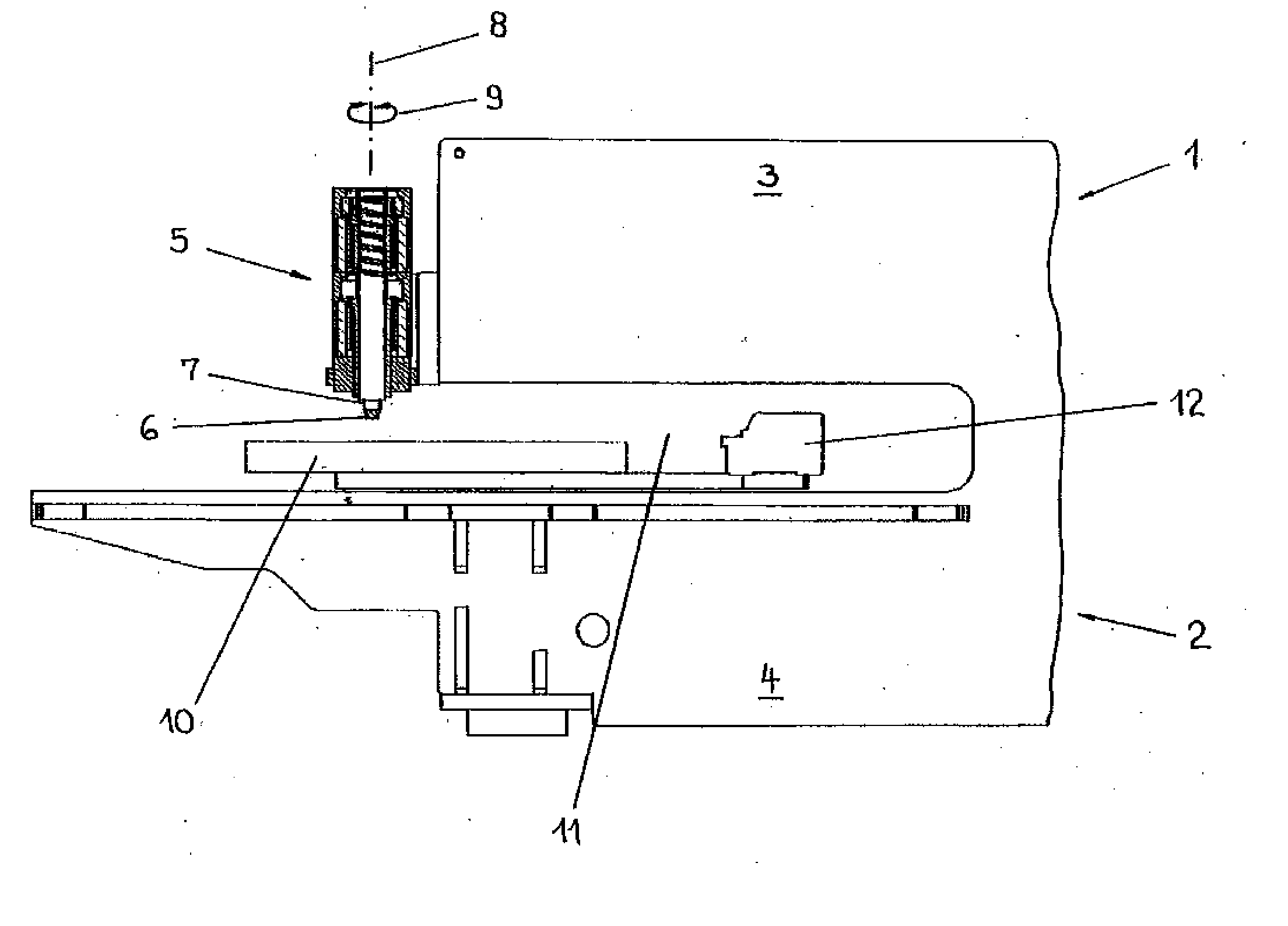
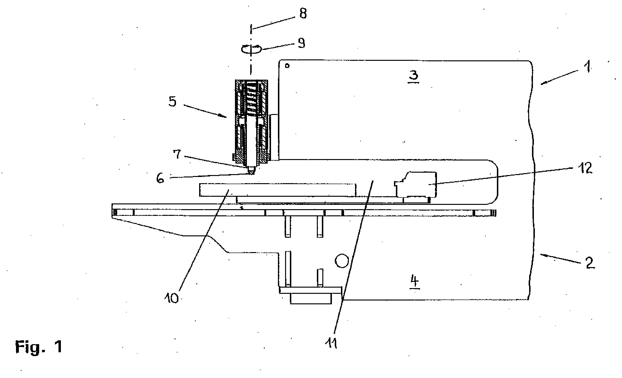
[0022] As shown in FIG. 1, a punching machine 1 has a C-shaped machine frame 2 with an upper frame member 3 and a lower frame member 4. An electric rotary / lifting drive 5 for a punching tool in the form of a punch 6 and for a tool bearing 7 equipped with the punch 6, is mounted at the free end of the upper frame member 3. By means of the rotary / lifting drive 5, the tool bearing 7 is movable in a straight line jointly with the punch 6 in the direction of a lifting axis 8 and is adjustable by rotation in the direction of a double arrow 9 about the lifting axis 8. Movements in the direction of the lifting axis 8 may be performed by the tool bearing 7 and the punch 6 during the working strokes for processing workpieces and during return strokes following the working strokes. Rotary adjustment of the tool bearing 7 and the punch 6 is performed to change the rotated position of the punch 6 relative to the lifting axis 8.

[0023] When machining a workpiece, (e.g., when punching sheets), the...


PUM


Abstract

There is provided a punch tool lift spindle. More specifically, in one embodiment, a punching machine including a tool bearing, a drive spindle coupled to the tool bearing, and a drive system configured to move the tool bearing axially along a lifting axis and to rotate the tool bearing about the lifting axis, the drive system including a motor system comprising a stator and a rotor internally coupled to the stator and a spindle nut coupled to the rotor and cooperating with the drive spindle, wherein the spindle nut is at least partially disposed within the stator.

Description

CROSS REFERENCE TO RELATED APPLICATIONS [0001] This application is a continuation of, and claims priority under 35 U.S.C. §120 to PCT / EP2005 / 005636, filed on May 25, 2005, and claims priority under 35 U.S.C. §119 from European application EP 04 012 523.9, filed May 27, 2004. Both of these references are hereby incorporated by reference.TECHNICAL FIELD [0002] This invention relates to industrial equipment, and more particularly to machines configured to cut or punch workpieces, such as metal sheets. BACKGROUND [0003] As those of ordinary skill in the art will appreciate, punching machines may be employed to punch holes or other cut-outs from a workpiece (e.g., a metal sheet). Typically, punching machines include a tool bearing for a punching tool and a rotary / lifting drive, which moves the tool bearing back and forth along a lifting axis to a working area of the punching machine. Also, the tool bearing is rotatably adjustable about the lifting axis. The punching machine may also incl...

Claims


Application Information

Patent Timeline
IPC IPC(8): B26D5/08B21D28/00B30B1/18
CPCY10T483/1795B21D28/002Y10T83/9428Y10T83/8794Y10T83/9476Y10T83/869
Inventor ERLENMAIER, WERNER
Owner TRUMPF WERKZEUGMASCHINEN GMBH & CO KG
Why Eureka
Try Eureka