General purpose distributed operating room control system

a control system and operating room technology, applied in the field of general purpose distributed operating room control system, control system and, can solve the problems of reducing the efficiency of performing various procedures, cumbersome utilization, and no known run time configurable system for operating more than one specific operating room devi

Inactive Publication Date: 2005-09-13
INTUITIVE SURGICAL OPERATIONS INC
View PDF34 Cites 106 Cited by
  • Summary
  • Abstract
  • Description
  • Claims
  • Application Information

AI Technical Summary

Benefits of technology

The patent describes an electronic system that can select and control multiple devices through a main controller. These devices may communicate with each other wirelessly or have direct connections to the main controller. This technology allows users to easily manage and operate various components without having to manually connect them all individually.

Problems solved by technology

The technical problem addressed in this patent is the difficulty for surgeons to efficiently perform surgical procedures because they have to manually operate multiple instruments with different controls, leading to reduced effectiveness and increased risk for patients. There is a need for a universal control system that allows surgeons to easily switch among several devices without having to constantly change interfaces or learning new methods. This would improve operational efficiency and reduce the duration of surgeries while minimizing risks for patients.

Method used


Image

  • General purpose distributed operating room control system
  • General purpose distributed operating room control system
  • General purpose distributed operating room control system

Examples


Embodiment Construction

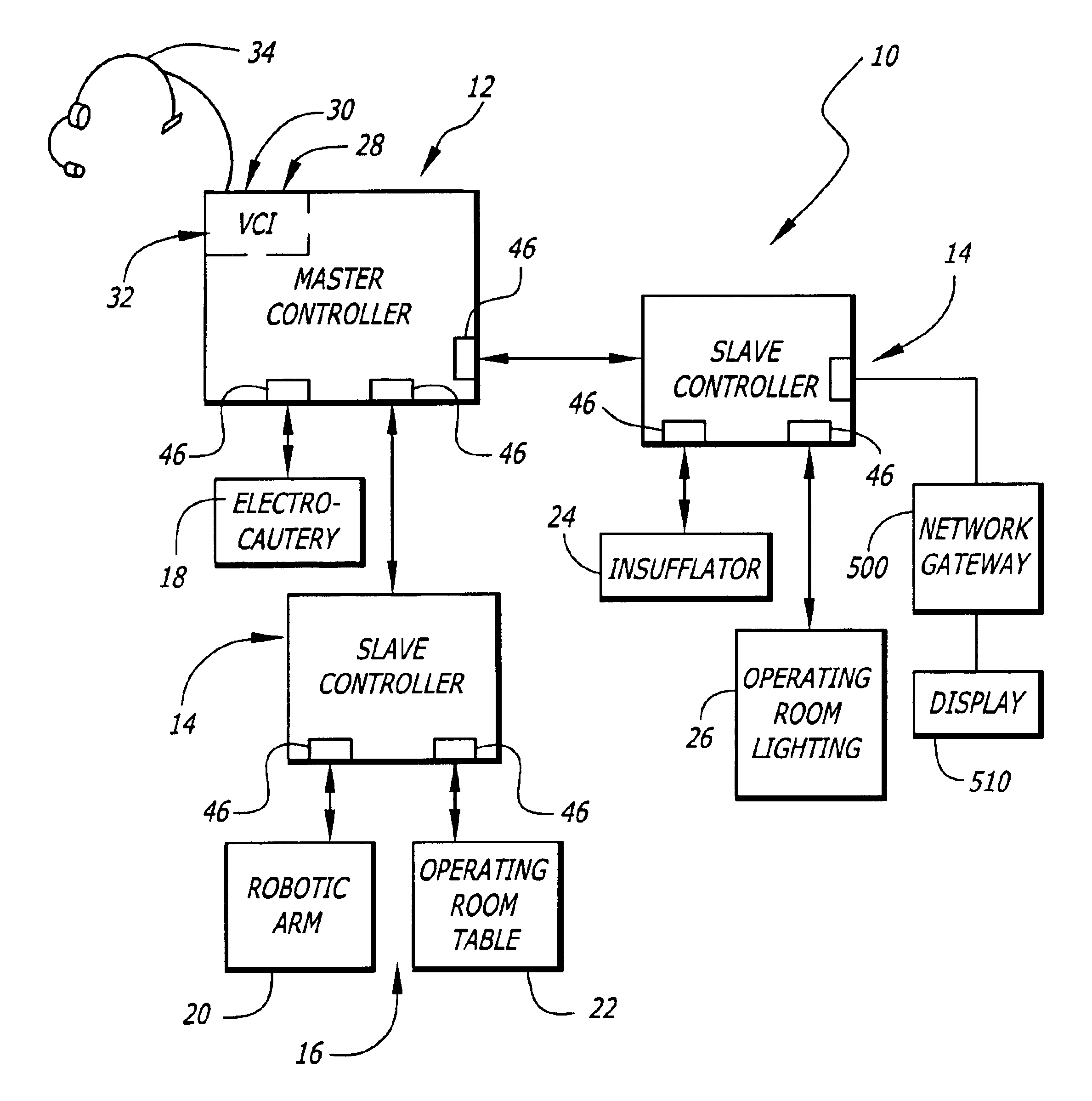
[0030]In accordance with the present invention, there is shown in FIG. 1 an operating room control system, generally at 10, in accordance with the present invention. The operating room control system, or control system 10, generally comprises a master controller 12, which is preferably attached to at least one slave controller 14. Although the exemplary preferred embodiment is shown as having both a master controller 12 and at least one slave controller 14 in electrical communication therewith, the control system 10 may be implemented with only a master controller 12 as will be described hereinbelow.

[0031]The master controller 12 is electrically connected to and in electrical communication with a plurality of devices 16 via a plurality of communication ports 46. Alternatively, the master controller 12 may be connected to any slave or specific medical device via wireless communications systems such as IR or RF signal transmitters and receivers on each of the master 12, slaves 14, and...


PUM


Abstract

The present invention pertains to control systems and provides a run time configurable control system for selecting and operating one of a plurality of operating room devices from a single input source, the system comprising a master controller having a voice control interface and means for routing control signals. The system additionally may include a plurality of slave controllers to provide expandability of the system. Also, the system includes output means for generating messages to the user relating to the status of the control system in general and to the status of devices connected thereto.

Description


Claims


Application Information

Patent Timeline
Owner INTUITIVE SURGICAL OPERATIONS INC
Why Eureka
Try Eureka