
Antenna with layered ground plane

a ground plane and antenna technology, applied in the field of solid-state antennas, can solve the problems of complex structure, high labor intensity, and difficulty in and achieve the effect of reducing labor intensity, reducing labor intensity, and reducing the difficulty of attracting the less skilled

Inactive Publication Date: 2005-09-13
LOCKHEED MARTIN CORP
View PDF10 Cites 15 Cited by
  • Summary
  • Abstract
  • Description
  • Claims
  • Application Information

AI Technical Summary

Problems solved by technology

Consequently, many of the terms used in the antenna arts have meanings which, while well understood in those arts, may be confusing to the less skilled.
Among the problems associated with the manufacture of array antennas is the need to associate with each elemental antenna (or group of elemental antennas) a beam control element, such as a phase shifter, an attenuator, or both.
The resulting structure is complex and expensive.
Many of the techniques described in these patents require substantial labor for making the large numbers of interconnections between the beamformer or control structure and the array of antenna elements.

Method used


Image

  • Antenna with layered ground plane
  • Antenna with layered ground plane
  • Antenna with layered ground plane

Examples


Embodiment Construction

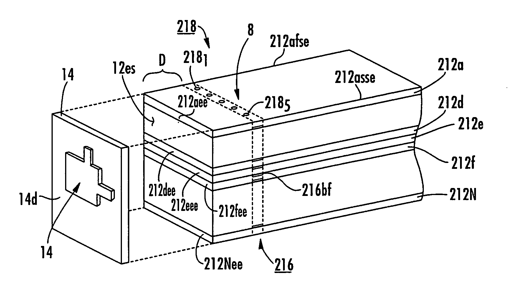
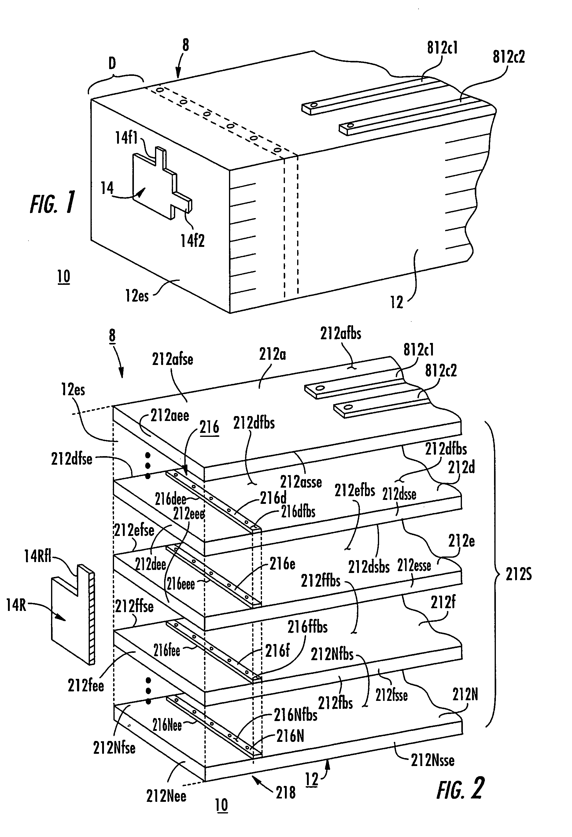
[0028]In FIGS. 1 and 2, an antenna structure 10 according to an aspect of the invention includes a body 12 made in the form of a stack 212S of mostly dielectric layers, more visible in the exploded view of FIG. 2, and also includes an electrically conductive radiating portion 14.

[0029]In FIG. 2, body 12 can be seen to be made up as a stack 212 of juxtaposed planar layers 212a, . . . , 212d, 212e, 212f, . . . , 212N. While the term “planar” suggests zero thickness, all real things have finite dimensions. The thicknesses of the layers are selected depending upon the detail or fineness with which the interior structure is to be defined and the desired final dimensions of the antenna structure 10. In FIG. 2, the uppermost layer is layer 212a. Several representative interior layers are designated 212d, 212e, and 212f. The lowermost layer is designated 212N, where N represents the total number of layers.

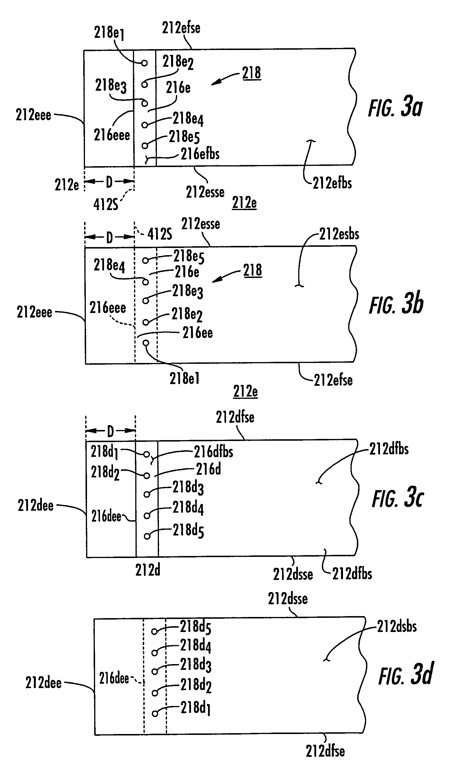
[0030]Referring now to FIG. 3a, representative interior layer 212e defines a first bro...


PUM


Abstract

An antenna structure for solid-state fabrication includes a ground plane comprising a stack of a plurality of planar conductors, each having its broad surfaces adjacent to, but insulated from, adjacent planar conductors. At least one edge of each conductor of the stack is registered with like edges of other conductors to define a discontinuous surface. A radiating element is spaced from the surface. Through vias extend between the conductors of the stack to form a conductive matrix. A feed for the radiating element extends toward, but does not contact, the matrix.

Description

FIELD OF THE INVENTION[0001]This invention relates to antennas, and more particularly to solid-state antennas.BACKGROUND OF THE INVENTION[0002]An antenna transduces electromagnetic waves between a guided mode and unguided radiation. The use of antennas for transmission and reception of such radiation antedates a full understanding of the properties of antennas. Consequently, many of the terms used in the antenna arts have meanings which, while well understood in those arts, may be confusing to the less skilled. For example, the term “antenna beam” is ordinarily understood to refer to the unguided radiation emitted from an antenna when guided waves are applied to its “feed” point or port. However, the term also applies to the response of an antenna to received unguided radiation as manifested by guided electromagnetic waves at the “feed” in the presence of plane wave unguided radiation, and the characteristics of the antenna beam in a reception mode are identical to the characteristi...

Claims


Application Information

Patent Timeline
IPC IPC(8): H01Q1/38
CPCH01Q1/38H01Q9/0435H01Q21/0025H01Q21/065
Inventor CADOTTE, JR., ROLAND
Owner LOCKHEED MARTIN CORP
Learn More