This helps you quickly interpret patents by identifying the three key elements:
Problems solved by technology
Method used
Benefits of technology
Benefits of technology
[0013]It is an object of the present invention to provide a photometric device capable of performing partial photometry and spot photometry at a lower luminance and more accurately determining a backlight situation, and a camera provided with the photometric device.
Problems solved by technology
10), a wide dynamic range cannot be ensured, thereby presenting a contradictory problem that the sensor fails to produce an output at a lower luminance, and thereby fails to accurately perform photometry.
In this case, however, the area for partial photometry cannot also be reduced in size in order to allow photometry at a lower luminance in the area for partial photometry.
It is thus impossible to accurately detect backlight.
In this case, when the plurality of areas serving as photometric areas have a large size, no problem occurs if a subject extends over all the photometric areas, but if a subject extends only over some of the photometric areas, accurate backlight detection is difficult to perform.
Method used
Image
Click on the blue label to locate the original text in one second.
Reading with bidirectional positioning of images and text.
Examples
first embodiment
(First Embodiment)
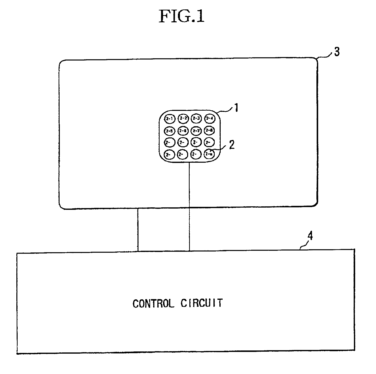
[0042]FIG. 1 illustrates the configuration of a photometric device according to a first embodiment of the present invention. It should be noted that description will be made herein assuming that the photometric device is provided for a camera (film camera, digital camera, video camera or the like).
[0043]In FIG. 1, reference numeral 1 refers to a first photometric sensor for performing photometry in a specific area (predetermined area: a central area of a picture in the first embodiment) of a picture. Reference numeral 2 refers to a second photometric sensor consisting of a group of small sensors (photoelectric conversion elements) 2-1, 2-2, . . . , 2-n for performing photometry in a plurality of subareas formed by dividing some or all of the specific area.
[0044]Reference numeral 3 refers to a third photometric sensor for performing photometry in a peripheral area around the specific area. Reference numeral 4 refers to a control circuit connected to the first photom...
second embodiment
(Second Embodiment)
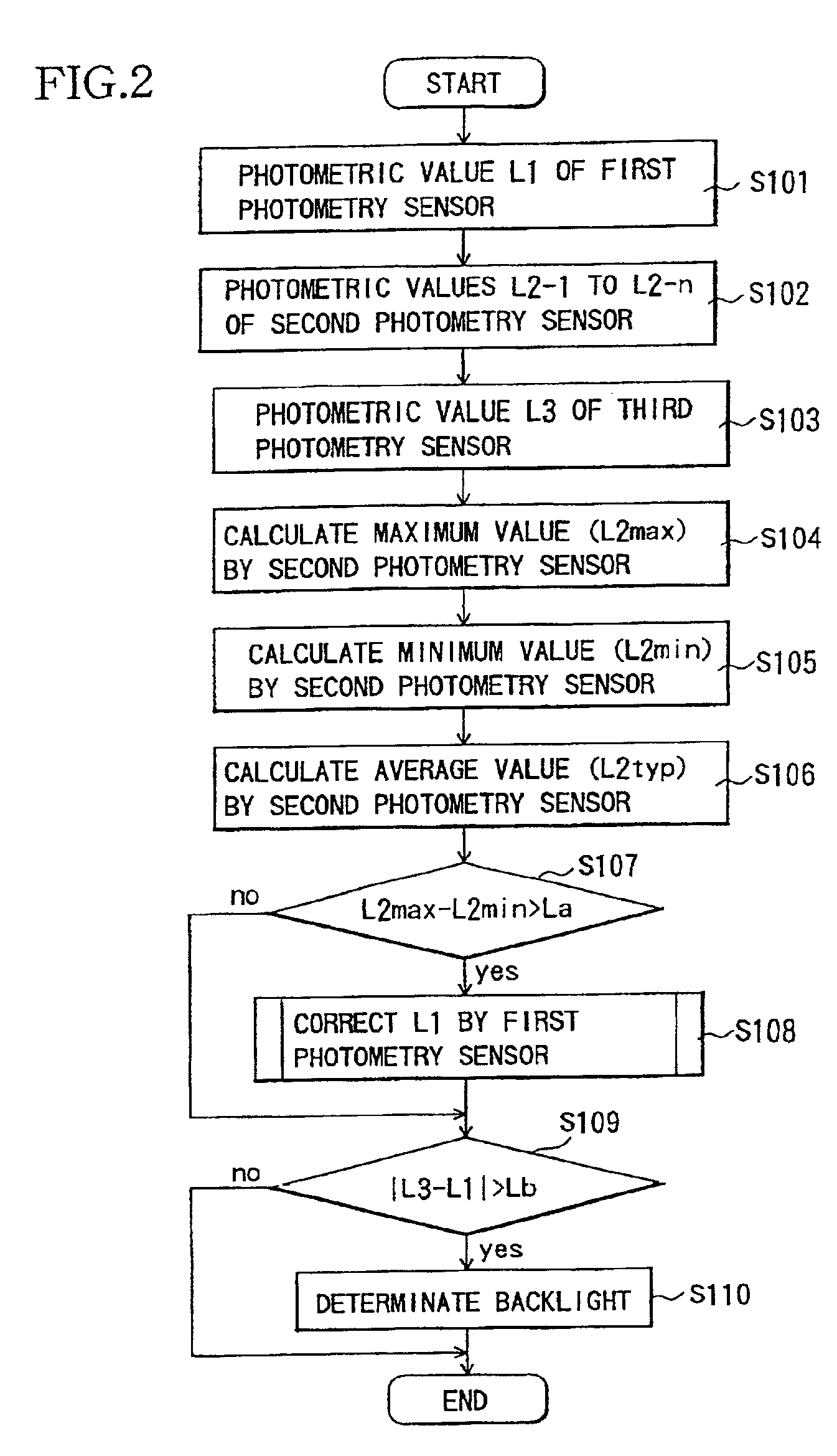
[0063]FIG. 3 shows a flow chart illustrating the operation of a photometric device according to a second embodiment of the present invention. The configuration of the photometric device in the second embodiment is identical to that in the first embodiment.
[0064]First, a control circuit 4 sends a control signal to a first photometric sensor 1 to cause it to perform photometry in a specific area, and then obtains a photometric value L1 thereof (S201).
[0065]Subsequently, the control circuit 4 sends a control signal to a group of sensors 2-1, 2-2, . . . , 2-n constituting a second photometric sensor 2 to cause them to perform photometry in respective subareas, and then obtains photometric values L2-1 to L2-n thereof (S202).
[0066]The control circuit 4 sends a control signal to a third photometric sensor 3 to cause it to perform photometry in a peripheral area, and then obtains a photometric value L3 thereof (S203).
[0067]Next, the control circuit 4 makes calculations to...
third embodiment
(Third Embodiment)
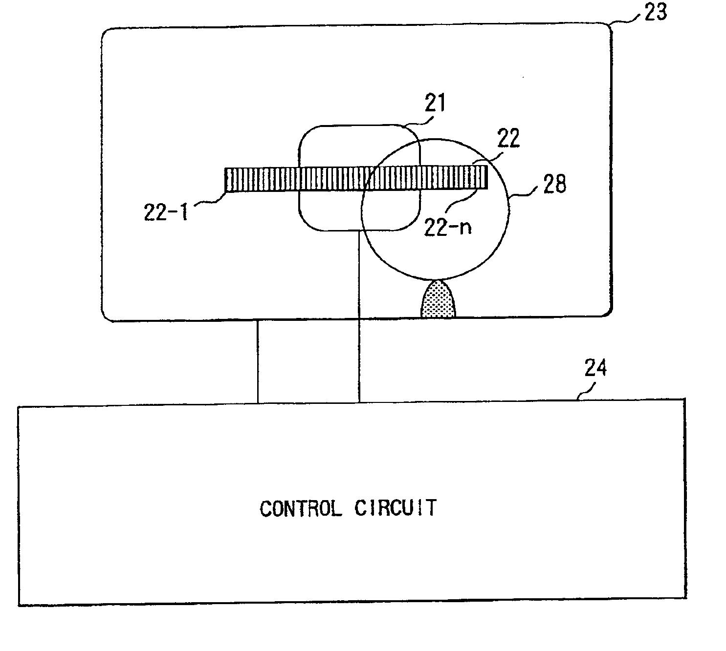
[0081]FIG. 4 illustrates the configuration of a photometric device according to a third embodiment of the present invention. It should be noted that description will be made herein assuming that the photometric device is provided for a camera.
[0082]In FIG. 4, reference numeral 12 refers to a group of photoelectric conversion elements (photometric sensors) arranged all over a photographic area, in which the individual photoelectric conversion elements are designated by reference numerals of 2-1 to 2-n.
[0083]Reference numeral 11 refers to photoelectric conversion elements 2-i to 2-j which are included in a specific area of the picture (predetermined area: an area surrounded by a black bold line in a central portion of the picture) and are called herein a first photometric sensor group. In the third embodiment, as later described, the sum of photocurrents from the photoelectric conversion elements 2-i, . . . , 2-j constituting the first photometric sensor group 11 is ...
PUM
Abstract
A photometric device according to the present invention performs the steps of: performing photometry in a first area of an overall area where photometry can be performed; performing photometry in a plurality of second areas, each included in the first area; and when a difference greater than a predetermined value exists among the photometric results in the plurality of second areas, correcting the photometric result in the first area based on the photometric results in the plurality of second areas and determining a backlight state exist based on the corrected photometric result. Alternatively, the photometric device performs the steps of: setting a reference value for determining a backlight state exist based on the difference between the photometric result in the first area and a photometric result in a peripheral area around the first area or a photometric result in the overall area; and when a difference greater than a predetermined value exists among the photometric results in the plurality of second areas, correcting the reference value based on the photometric results in the plurality of second areas. In this manner, partial photometry and spot photometry can be performed at a lower luminance, and a backlight atate can be more accurately determined.
Description
BACKGROUND OF THE INVENTION[0001]1. Field of the Invention[0002]The present invention relates to a photometric device provided for a camera or the like, and more particularly to a photometric device capable of determining a backlight situation.[0003]2. Description of the Related Art[0004]In recent years, cameras capable of partial photometry or spot photometry have become widely used, in which luminance is measured in a specific portion of a photographic area and photographs are taken on the basis of the information on the luminance. Since these cameras faithfully reproduce brightness of a portion which a photographer wishes to shoot, they are considerably effective especially when a subject is small or when a great difference exists in luminance between a subject and its surroundings.[0005]Another proposed technique is to measure luminance in a central portion and a peripheral portion of a picture, determine from the difference between them that a scene to be photographed is a back...
Claims
Application Information
Patent Timeline
Application Date:The date an application was filed.
Publication Date:The date a patent or application was officially published.
First Publication Date:The earliest publication date of a patent with the same application number.
Issue Date:Publication date of the patent grant document.
PCT Entry Date:The Entry date of PCT National Phase.
Estimated Expiry Date:The statutory expiry date of a patent right according to the Patent Law, and it is the longest term of protection that the patent right can achieve without the termination of the patent right due to other reasons(Term extension factor has been taken into account ).
Invalid Date:Actual expiry date is based on effective date or publication date of legal transaction data of invalid patent.

