
Electronically programmable multimode circuit

a multi-mode, electrically programmable technology, applied in pulse manipulation, gated amplifiers, pulse techniques, etc., can solve the problems of fixed topology and prior art not addressing the situation, and achieve the effect of improving the ability to focus the antenna beam width, improving the ability to control gain instead of loss, and fine resolution

Active Publication Date: 2005-09-13
NORTHROP GRUMMAN SYST CORP
View PDF4 Cites 44 Cited by
  • Summary
  • Abstract
  • Description
  • Claims
  • Application Information

AI Technical Summary

Benefits of technology

[0016]It is an advantage of the present invention that system requirements may be modified after the transceiver hardware is implemented, and the same transceiver hardware may be reprogrammed to change the transceiver module performance characteristics such as gain, phase shift, add and / or remove electronic hardware such as mixers, phase shifters, attenuators, and amplifiers.
[0017]It is another feature of the present invention that the programmable electronic circuit may synthesize angles within a 360-degree window with very fine resolution and provide gain control instead of loss. For example, when programming three dualgate FETs of the first and the second FET gate array within respectively a first and a second functional blocks as variable periphery amplifiers (VPAs), it is possible to achieve 11.5 degree antenna beams pointing accuracy. Further, the fine resolution and gain control provides a better means to focus the antenna beam width and increase the antenna pointing accuracy for target acquisition and tracking.
[0018]It is another advantage that the present invention may be electronically programmable as a phase shifter within a compact real estate area at low frequencies compared with convention delay-line phase shift approaches. Additionally, the compactness of the multimode transceiver circuits permits the transceiver circuits to be coupled near each antenna element of an array, which location minimizes noise figure for receiver applications and maximizes output power for transmitter applications. Another advantage is that the entire transceiver circuit would be integrated into one circuit. The one circuit approach eliminates the need for separate functional blocks, ultimately decreasing the part count and improving yield and reliability because amplifiers with high part counts complicate the manufacturing process and usually lead to a low mean time to failure and rework. The one circuit approach would be ideal for wireless data transmission and acquisition such wireless cell phones.

Problems solved by technology

A fixed topology is problematic if modified system requirements require disassembly of a transceiver module to modify or to replace electronic hardware components.
However, the prior art does not address the situation when modified system requirements require the removal or the addition of electronic hardware components from an existing electronic system.

Method used


Image

  • Electronically programmable multimode circuit
  • Electronically programmable multimode circuit
  • Electronically programmable multimode circuit

Examples


Embodiment Construction

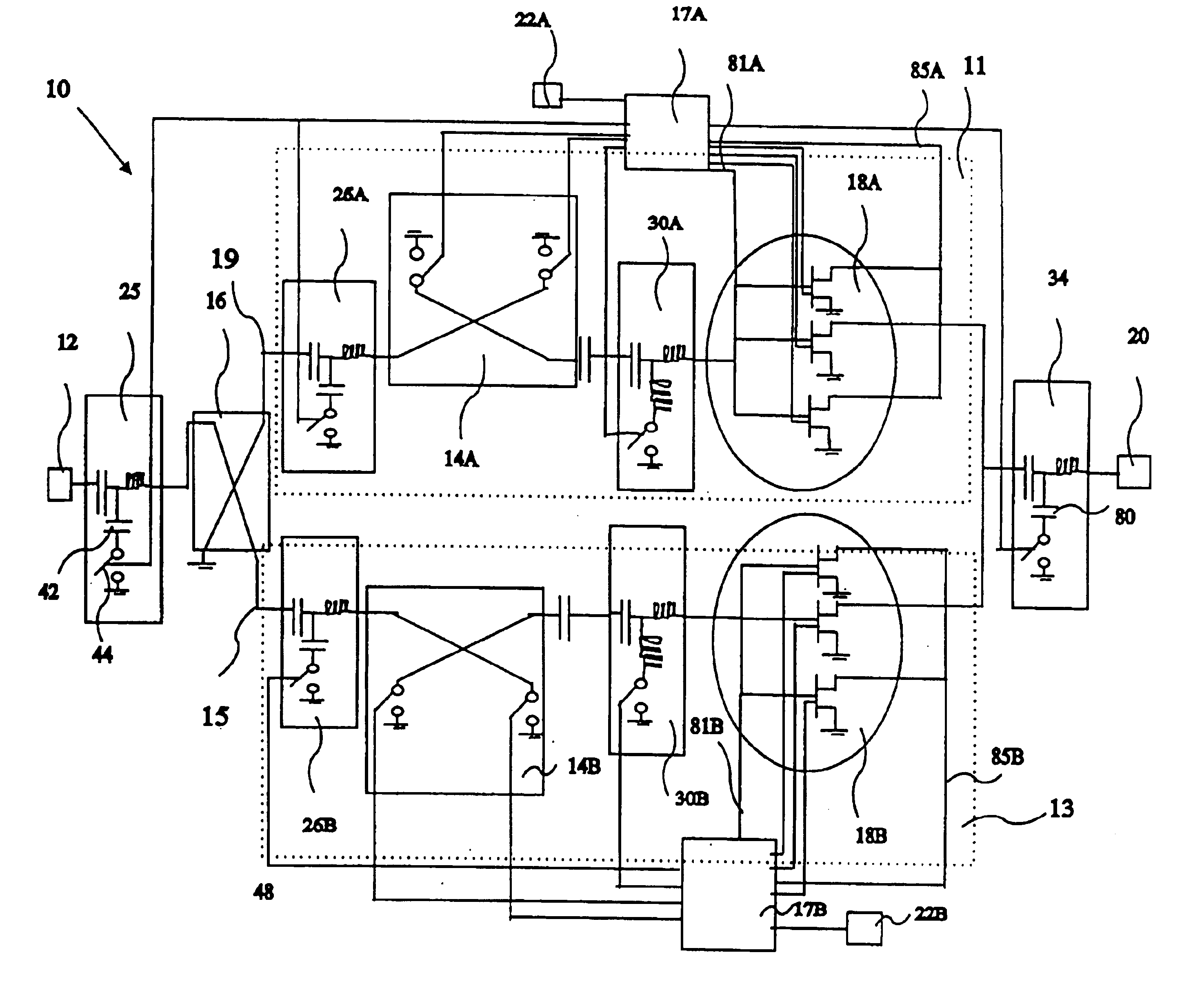
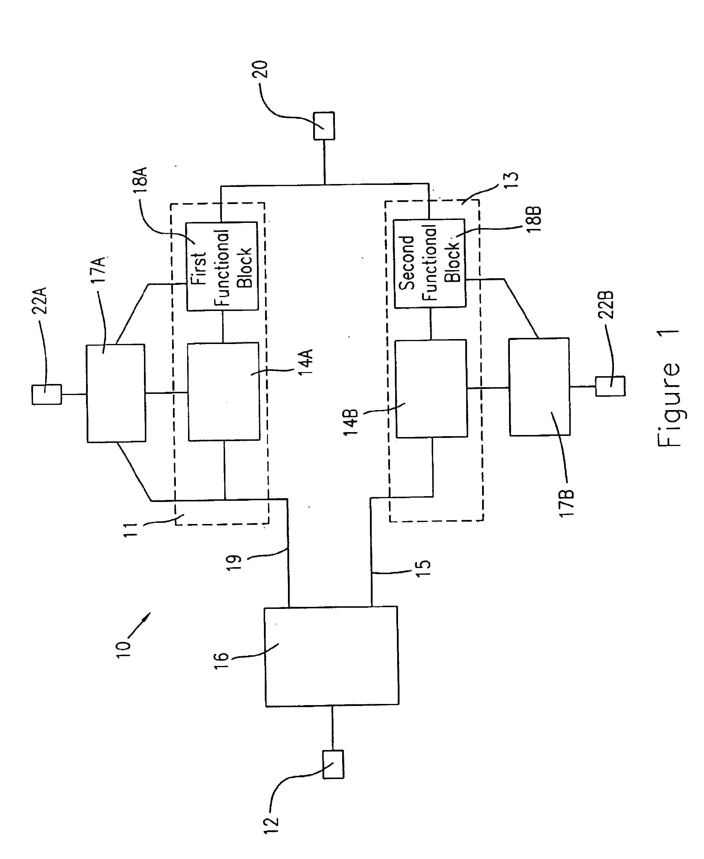
[0030]Referring particularly to FIG. 1, a block diagram of an electronically programmable multimode circuit 10 of the present invention is shown, which electronically programmable multimode circuit 10 may be programmed or re-programmed for at least one mode to perform various operations on a signal. Further, electronically programmable multimode circuit 10 includes a first path 11 and a second path 13. For purposes of describing the present invention, said electronically programmable multimode circuit 10 is described for transmitter and receiver applications. Further, it shall be noted that the present invention may be used for applications other than transmitter and receiver applications.

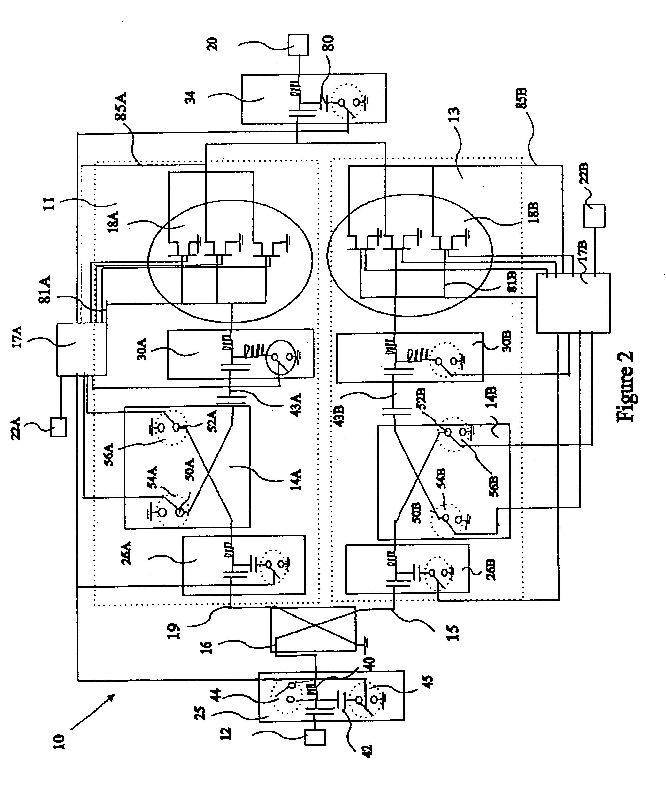
[0031]The electronically programmable multimode circuit 10 comprises a first port 12, a second port 20, electrodes 22A, 22B, control circuits 17A, 17B, a phase shift coupler 16, a first phase shift device 14A, a second phase shift device 14B, a first functional block 18A, and a second functional bl...


PUM


Abstract

An electronically programmable multimode circuit is described. More particularly, the present invention is an electronically programmable multimode circuit that includes a first path and a second path wherein a mode and a signal directional flow direction is controlled through the selective biasing of the first path and the second path. A multimode circuit is produced that contains modes such as a phase shifter mode, an IQ modulation mode, an amplifier mode, a mixer mode, and a multiplier mode.

Description

FIELD OF THE INVENTION[0001]The present invention relates to an electronically programmable, multimode circuit for electronic systems. More particularly, the present invention relates to an electronically programmable, multimode Monolithic Microwave Integrated Circuit (MMIC) that allows a user to electronically program and to reprogram the electronic hardware components so that the same multimode circuit may be utilized for multiple receive and transmit applications. For instance, the multimode circuit may be programmed for at least one mode selected from a group consisting of a phase shifter mode, an In-Phase and Quadrature (IQ) modulator mode, an amplifier mode, an attenuator mode, a multiplier mode, and a mixer mode. Multiple electronically programmable, multimode circuits may be cascaded to achieve a user desired electronic system functionality.DESCRIPTION OF THE PRIOR ART[0002]Electronic systems require electronic hardware to perform processing on an electronic signal, which pr...

Claims


Application Information

Patent Timeline
Patent Type & Authority Patents(United States)
IPC IPC(8): H03F3/72H03F3/20H03F1/02H03F3/21H03C3/40
CPCH03C3/40H03F1/0277H03F3/211H03F3/72H03F2200/372
Inventor YANG, JEFFREY MING-JERNISHIMOTO, MATTLAN, XINGBATTUNG, MICHAELWANG, ROBERTCHUNG, YUN-HO
Owner NORTHROP GRUMMAN SYST CORP
Learn More