
Apparatus for positioning and marking a location of an EMG electrode

a technology of electromyography and apparatus, which is applied in the field of apparatus for positioning and marking the location of an electromyography (emg) electrode, can solve the problems of malfunction of the prosthesis, difficult for the examinee to determine the location of the emg electrode, and more difficult for the examinee to detect the emg electrode location, etc., to achieve the effect of easy positioning and easy marking

Inactive Publication Date: 2005-09-13
ELECTRONICS & TELECOMM RES INST
View PDF8 Cites 58 Cited by
  • Summary
  • Abstract
  • Description
  • Claims
  • Application Information

AI Technical Summary

Benefits of technology

[0007]It is, therefore, an object of the present invention to provide an apparatus for positioning and marking a location of an EMG electrode to easily position a location of an EMG electrode depending on a motion of the body of an examinee and to easily mark the location of the EMG electrode on the skin of an examinee by using the fact an auditory organ, i.e., an ear, has a frequency analyzing function as well as a level analyzing function.

Problems solved by technology

Since the inaccurate location of the EMG electrode results in a malfunction of the prosthesis or the HCI due to a noise of the body itself, the location of the EMG electrode must be precisely detected depending on the motion of the body, e.g., a bending of an arm.
Since the prosthesis or the HCI apparatus must be occasionally attached or detached as necessity requires, it is difficult for the examinee himself / herself to detect the location of the EMG electrode.
Since, however, an EMG sensor is usually attached around one arm of the examinee, it is more difficult for the examinee to determine the location of the EMG electrode and to mark same with a pen taken in the hand of the other arm of the examinee on which no EMG sensor is attached.

Method used


Image

  • Apparatus for positioning and marking a location of an EMG electrode
  • Apparatus for positioning and marking a location of an EMG electrode
  • Apparatus for positioning and marking a location of an EMG electrode

Examples


Embodiment Construction

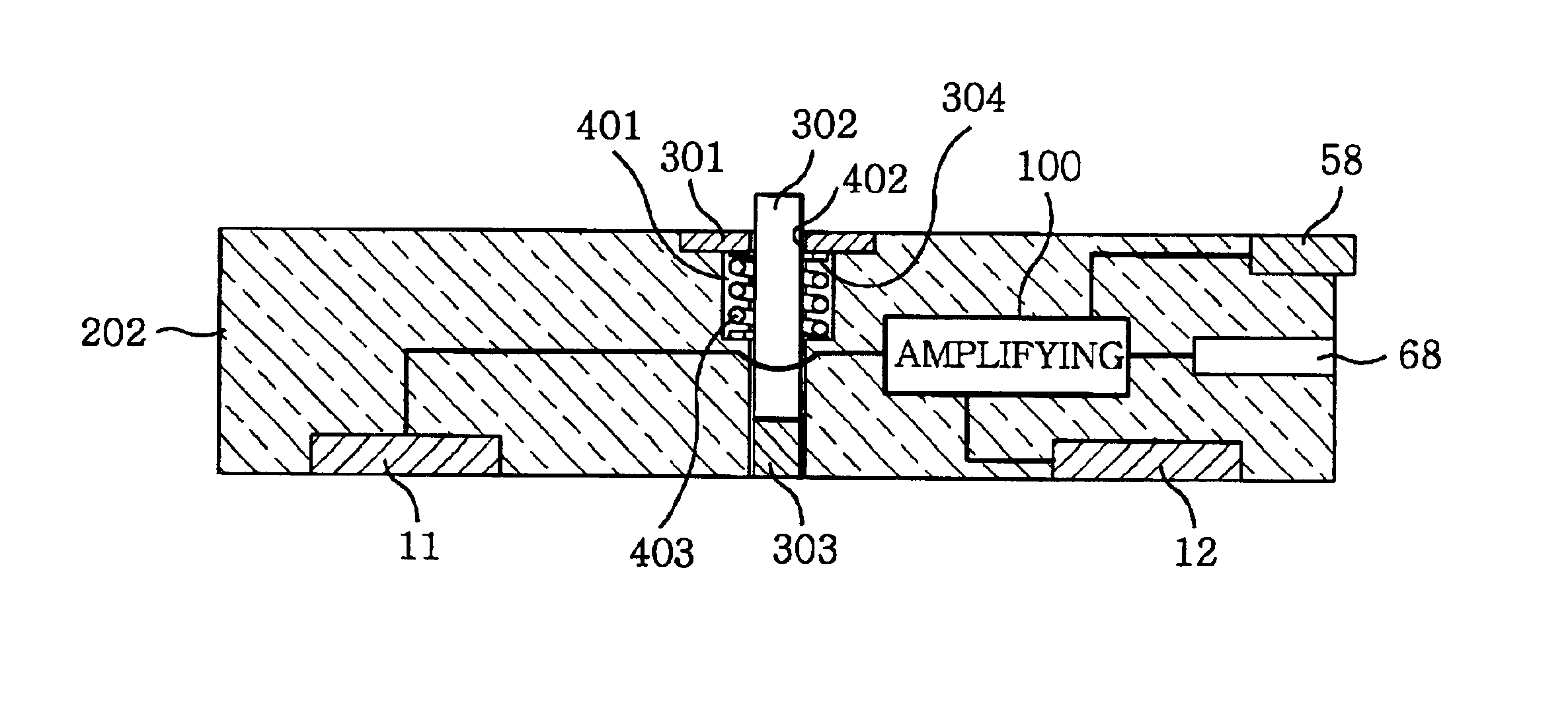
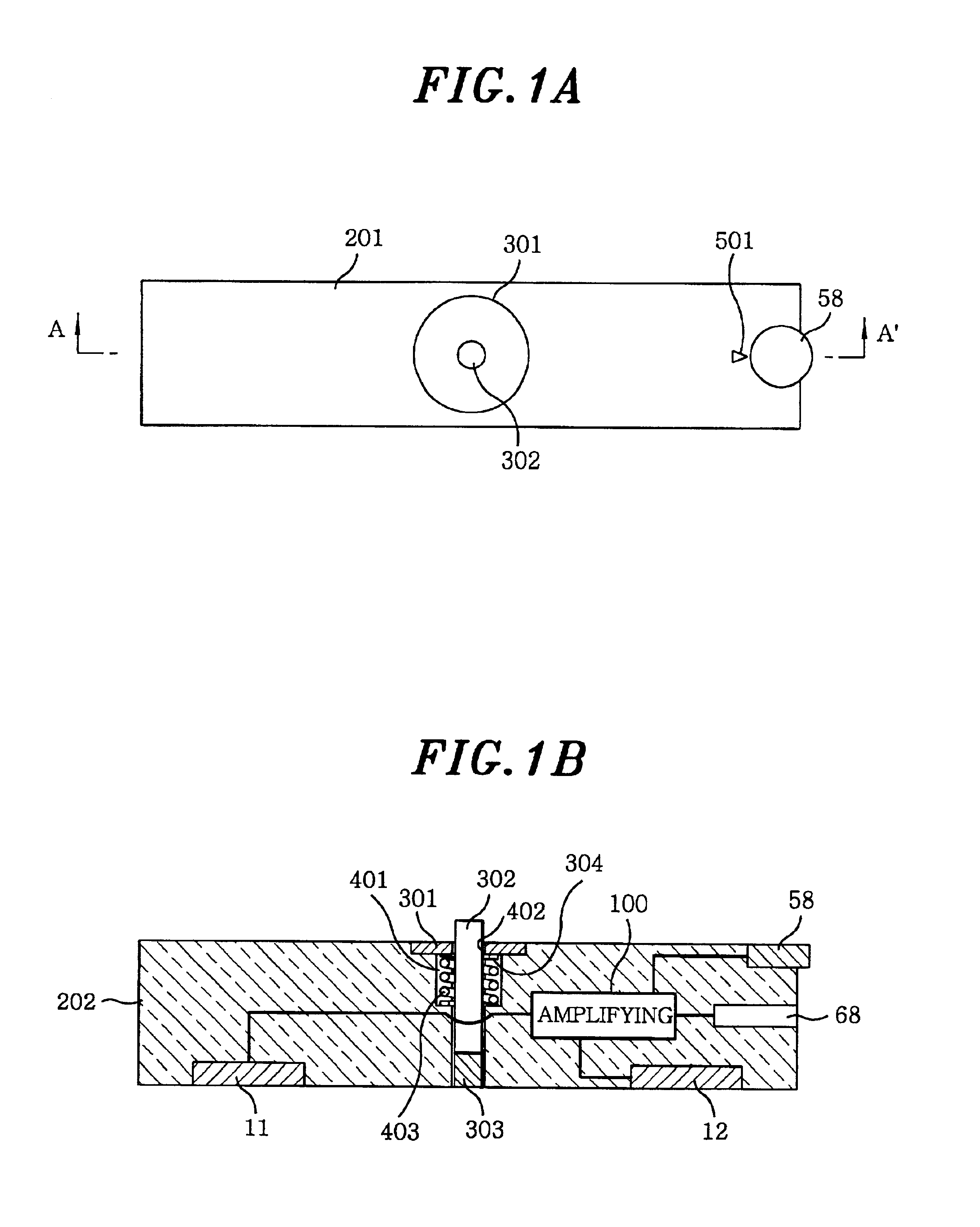
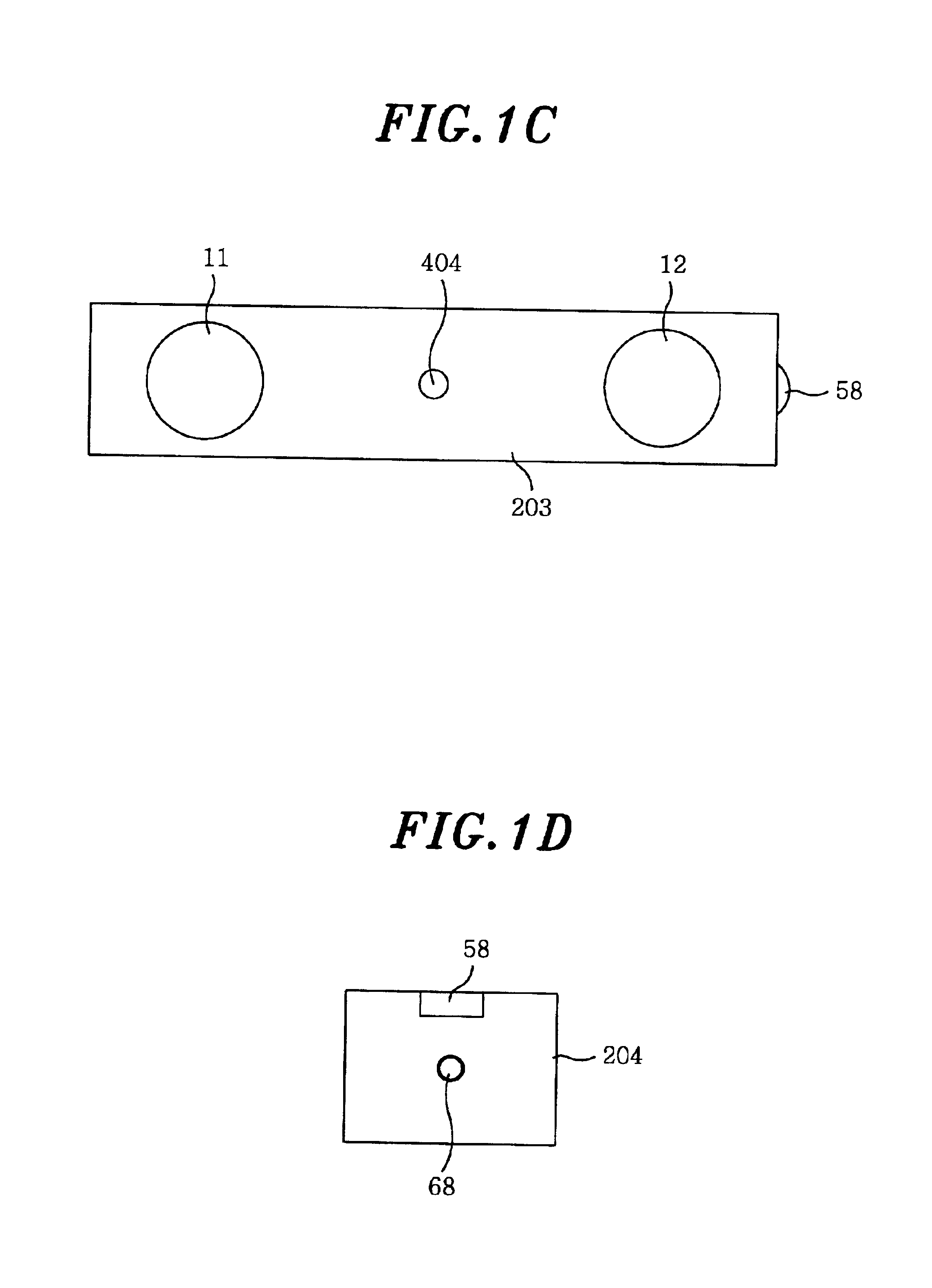
[0018]Referring to FIGS. 1A to 1D, there is shown a schematic view for an apparatus for positioning and marking a location of an electromyography (EMG) electrode in accordance with the present invention. FIGS. 1A to 1D represent a plan view, a cross-sectional view taken along a line A-A′, a back view and a right side view of the apparatus in accordance with the present invention, respectively.

[0019]The apparatus includes a rectangular parallelepiped housing 201, 202, 203 and 204, a first and a second EMG sensors 11 and 12, an amplifying circuit 100, a gain control lever 58, an audio output terminal 68, a marking lever 302, a marking tap 303, an elastic material housing space 401, an elastic material 403 and a marking lever cap 301.

[0020]The first and the second EMG sensors 11 and 12 for receiving a first and a second EMG signals are installed on a back surface of the housing 201, 202, 203 and 204 and each of the first and the second EMG sensors 11 and 12 has a sensing surface which ...


PUM


Abstract

An apparatus for positioning and marking a location of an electromyography (EMG) electrode includes a housing having a back surface, an EMG sensor for receiving the EMG signal, an amplifying circuit for amplifying the EMG signal to generate an amplified EMG signal and an audio output terminal for outputting the amplified EMG signal as the audio EMG signal. The examinee may directly position and mark the location of the EMG electrode and may easily detect the fatigue rate of the muscle or the abnormal condition of the muscle by using the sound of the audio equipment.

Description

FIELD OF THE INVENTION[0001]The present invention relates to an apparatus for positioning and marking a location of an electromyography (EMG) electrode, and, more particularly, to an apparatus for converting an EMG signal to an audio EMG signal to easily position a location of an EMG electrode and to easily mark the location thereof on a skin of a human body.BACKGROUND OF THE INVENTION[0002]The EMG signal represents an electrical signal associated with an activity of a skeletal muscular fiber and has been used to control a prosthesis or to develop a human computer interface (HCI) technology.[0003]In order to control the prosthesis to develop an EMG based HCI technology, a sensor to detect the EMG signal must be attached around a portion, e.g., an arm, of a body. Since the inaccurate location of the EMG electrode results in a malfunction of the prosthesis or the HCI due to a noise of the body itself, the location of the EMG electrode must be precisely detected depending on the motion...

Claims


Application Information

Patent Timeline
Patent Type & Authority Patents(United States)
IPC IPC(8): A61B5/0488A61B5/04
CPCA61B5/0488A61B5/061A61B5/6842A61B2562/0209A61B2562/043A61B5/7415A61B5/389
Inventor JEONG, HYUKKIM, HYUN BINKIM, KI HOKIM, KI HONGKIM, HONG KEEMYUNG, HYUNGHYME, SANG WONLEE, KI SUKKIM, YONG WANCHOI, JIN SUNG
Owner ELECTRONICS & TELECOMM RES INST
Learn More