Refrigerator with an icemaker

a technology of refrigerator and icemaker, which is applied in the field of refrigerators, can solve the problems of user inconvenience, temperature rise of freezers, and user stooping back, and achieve the effects of improving the structure of supplying ice, convenient height for users, and convenient us

Active Publication Date: 2005-09-20
LG ELECTRONICS INC
View PDF12 Cites 116 Cited by
  • Summary
  • Abstract
  • Description
  • Claims
  • Application Information

AI Technical Summary

Benefits of technology

[0013]An object of the present invention is to provide a refrigerator with an icemaker, the refrigerator having an improved structure and including a dispenser at a convenient height for a user to use.
[0014]Another object of the present invention is to provide a refrigerator with an icemaker, the refrigerator having an improved structure for supplying ice to a user at an outside thereof without opening the door.

Problems solved by technology

Therefore, there is an inconvenience that the user has to stoop his / her back for using the dispenser.
However, in this case, there is an inconvenience that the user has to open the door and separates the ice stored in the ice tray from the ice tray for using the ice.
Also, when the door is open for using the ice, cool air in the freezer leaks out to the outside thereof and the temperature of the freezer goes up.
Therefore, compressor is required to work more and there is a problem that energy is wasted.

Method used


Image

  • Refrigerator with an icemaker
  • Refrigerator with an icemaker
  • Refrigerator with an icemaker

Examples


first embodiment

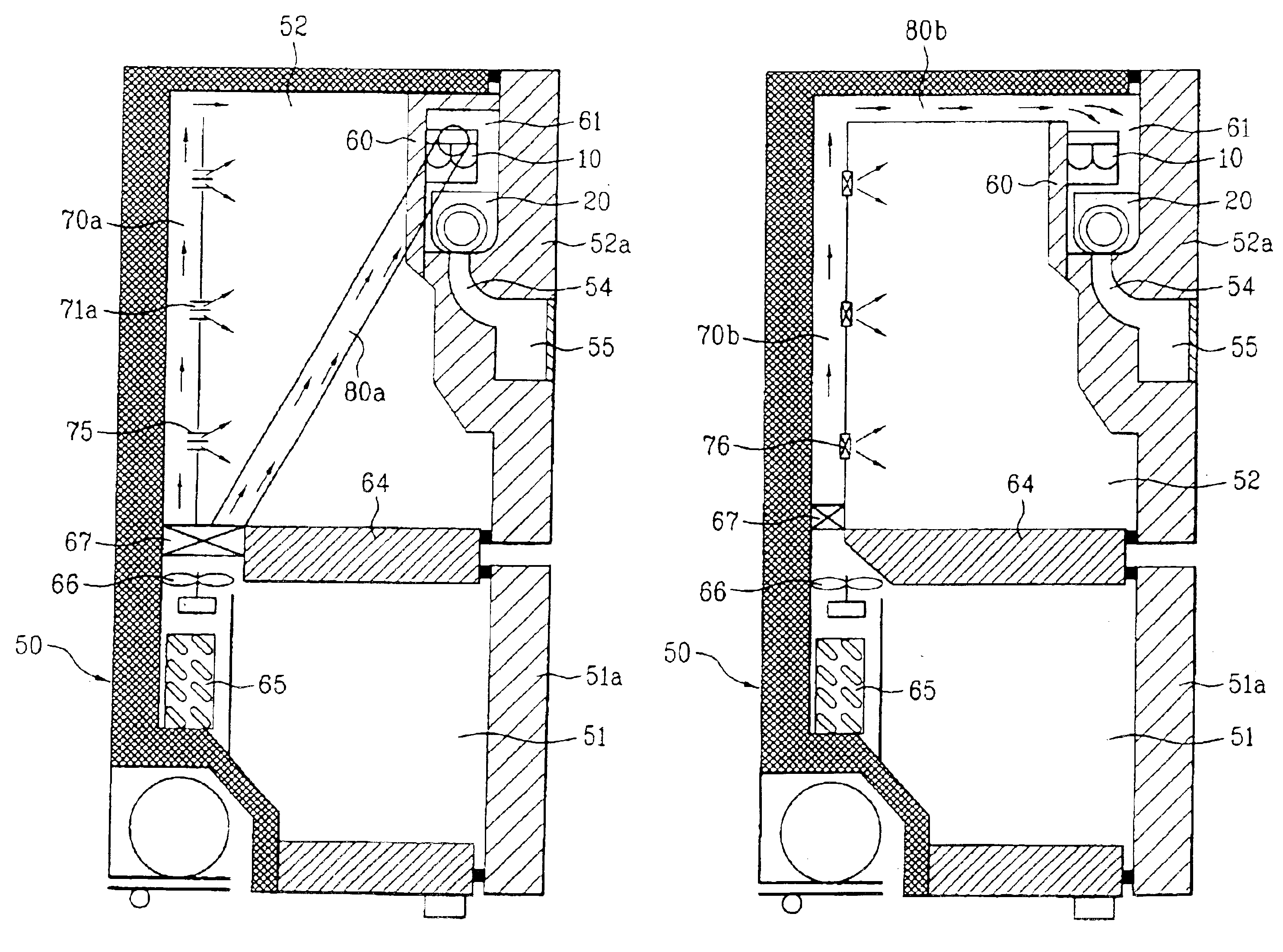
[0077]First, referring to FIGS. 5 and 6, the first embodiment will be described. Referring to FIGS. 5 and 6, a cooling chamber 52 is provided at upper part in a cabinet 50 and a freezer 51 is provided at lower part in the cabinet 50. In this case, the cooling chamber 52 and the freezer 51 are divided via a mullion 64 as illustrated in FIG. 6.

[0078]Referring to FIG. 6, an evaporator 65 is provided at the freezer 51 and a fan 66 is provided near the evaporator 65. Accordingly, cool air generated near the evaporator 65 is supplied to the freezer 51 and the cooling chamber 52. Meanwhile, the evaporator 65 is not provided at only the freezer 51. That is, although not illustrated, the evaporator can be provided at the cooling chamber. Furthermore, a plurality of evaporators 65 can be provided at the freezer 51 and the cooling chamber 51. However, an embodiment providing one evaporator 65 at the freezer 51 is illustrated in FIG. 6. Hereinafter, the embodiment will be described.

[0079]Meanwh...

second embodiment

[0095]Referring to FIG. 7, in the refrigerator the first and second ducts 70b and 80b are communicated with each other.

[0096]In this case, a first end of the first duct 70b is provided adjacent to the evaporator 65 and a second end of the first duct 70b is provided in the cooling chamber 52. It is desirable that the first duct 70b is provided on a rear wall of the cooling chamber 52 as illustrated in FIG. 7 and the second end of the first duct 70b is provided at the upper part of the cooling chamber 52.

[0097]Meanwhile, the plurality of holes is provided at the first duct 70b. The holes are for supplying cool air to the cooling chamber 52 through the first duct 70b. A damper 76 is provided at the holes as illustrated in FIG. 7. When the damper 76 is provided at the holes, the amount of cool air supplied to the cooling chamber 52 through the holes is controlled. In the mean time, although it is not illustrated, the louver is provided at the holes as illustrated in FIG. 6.

[0098]The fi...


PUM


Abstract

Disclosed is a refrigerator having an improved structure for supplying ice to an outside through a dispenser provided at a door. A cabinet includes a freezer and a cooling chamber. A case having a cavity therein is provided at the door opening and closing the cooling chamber. A first duct is provided in the cabinet for supplying cool air generated around the evaporator to the cooling chamber and a second duct is provided in the cabinet for supplying the cool air to the cavity. The icemaker is provided at the cavity for producing ice and the ice container is provided at the cavity for storing the ice. The dispenser is provided at the door in communication with the cavity for supplying the ice to a user outside.

Description

CROSS-REFERENCE TO RELATED APPLICATIONS[0001]This application claims the benefit of Korean Application No. P2003-65162, filed on Sep. 19, 2003, which is hereby incorporated by reference as if fully set forth herein.BACKGROUND OF THE INVENTION[0002]1. Field of the Invention[0003]The present invention relates to a refrigerator, and more particularly, to a refrigerator with an icemaker having a structure for supplying ice from an outside of the refrigerator through a dispenser.[0004]2. Discussion of the Related Art[0005]A refrigerator is an apparatus for taking storage of foods freshly for a long-term period. Such refrigerator has a food-storage chamber therein. The food-storage chamber is always maintained at a low temperature by a refrigerating cycle for keeping food fresh.[0006]The food-storage chamber is divided into a plurality of storage chambers having different characteristics from each other such that a user can choose a food-storage method in consideration of a kind, a charac...

Claims


Application Information

Patent Timeline
Patent Type & Authority Patents(United States)
IPC IPC(8): F25C5/00F25C1/24F25D17/08F25C5/04F25D11/02F25D17/04F25D17/06F25D23/04
CPCF25C5/005F25D17/045F25D17/065F25C5/046F25C2400/10F25D2317/062F25D2317/0665F25D2500/02F25C5/22F25C1/24
Inventor KIM, SEONG JAELEE, MYUNG RYULSEO, CHANG HOCHUNG, SUNE HOON
Owner LG ELECTRONICS INC
Why Eureka
Try Eureka