
Sheet feeding apparatus having an adaptive air fluffer

a feeder apparatus and fluffer technology, applied in the field of electronic reprographic printing system, can solve the problems of low pressure relief across the wide range of media types prescribed by various combinations of fluffer pressure settings and configurations, and all system pressure losses

Inactive Publication Date: 2005-09-20
XEROX CORP
View PDF4 Cites 6 Cited by
  • Summary
  • Abstract
  • Description
  • Claims
  • Application Information

AI Technical Summary

Problems solved by technology

It is in the initial separation of the individual sheets from the media stack where the greatest number of problems occur which, in some cases, can be due to up curl and down curl in sheets which generally occur randomly in the document stack.
The venturi fluffer provided a wide throat cross section that delivered sufficient air volume to maintain sheet separation, once achieved, but at an insufficient pressure necessary to break up sheet pairings observed during testing.
Various combinations of fluffer pressure settings and configurations provided little relief across the wide range of media types prescribed.
All of the systems have pressure losses due to air flowing above the stack.

Method used


Image

  • Sheet feeding apparatus having an adaptive air fluffer
  • Sheet feeding apparatus having an adaptive air fluffer
  • Sheet feeding apparatus having an adaptive air fluffer

Examples


Embodiment Construction

[0009]While the present invention will hereinafter be described in connection with preferred embodiments, it will be understood that it is not intended to limit the invention to a particular embodiment.

[0010]For a general understanding of the features of the present invention, reference is made to the drawings. In the drawings, like reference numerals have been used throughout to designate like elements. It will become evident from the following discussion that the present invention and the various embodiments set forth herein are suited for use in a wide variety of printing and copying systems, and are not necessarily limited in its application to the particular systems shown herein.

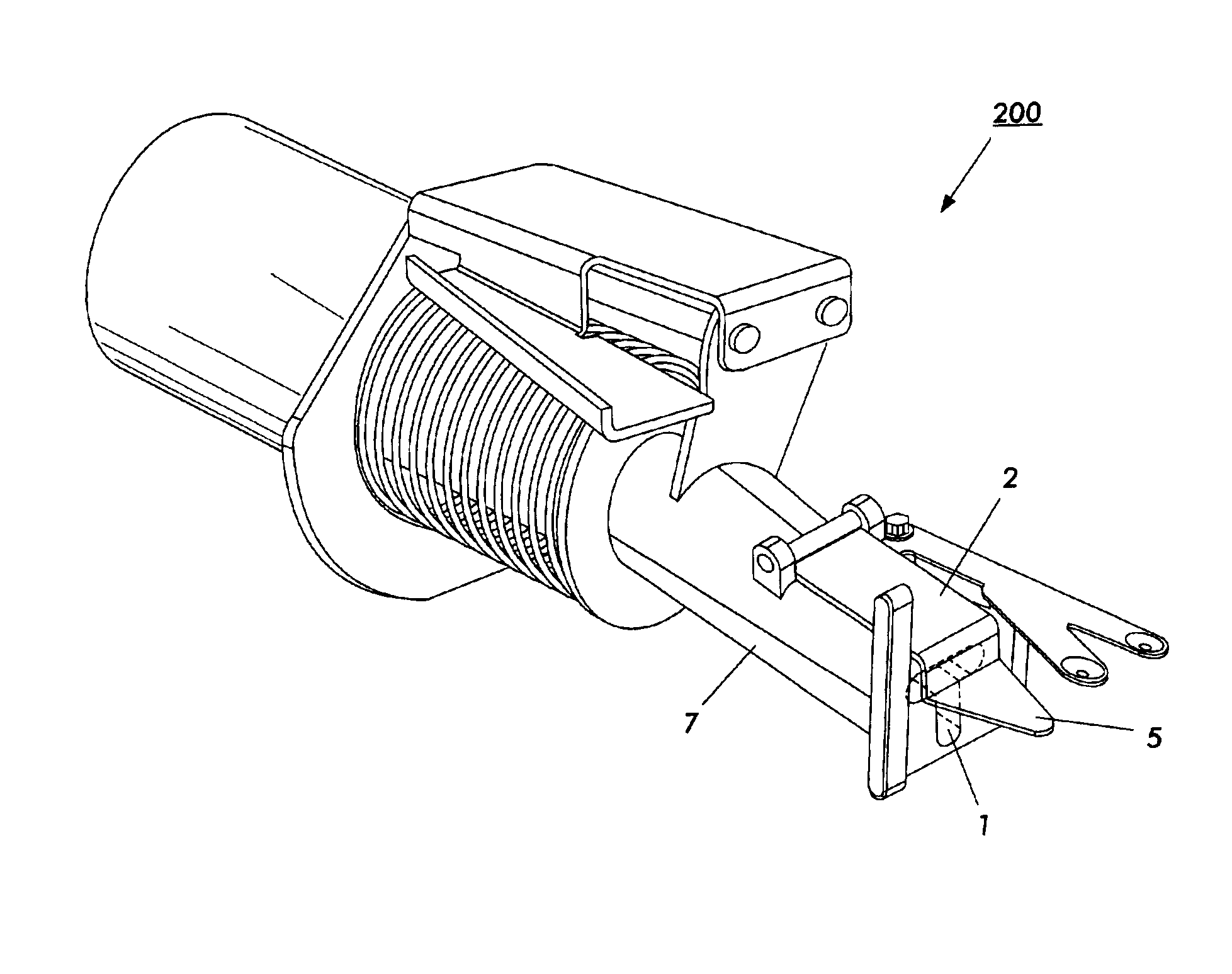
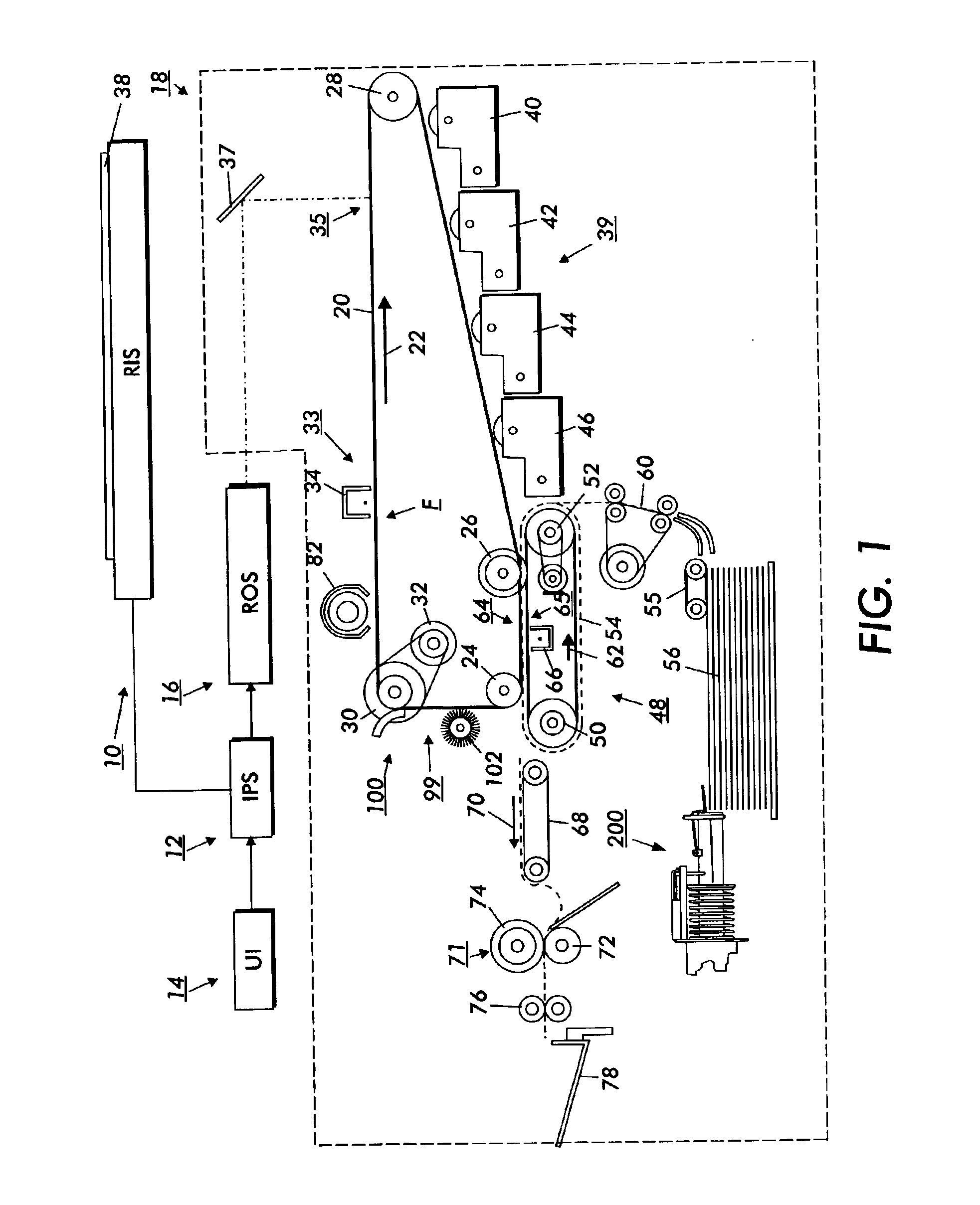
[0011]By way of a general explanation, FIG. 1 is a schematic elevational view showing an electrophotographic printing machine which incorporates features of the present invention therein. It will become evident from the following discussion that the present invention is equally well suited for use in a ...


PUM


Abstract

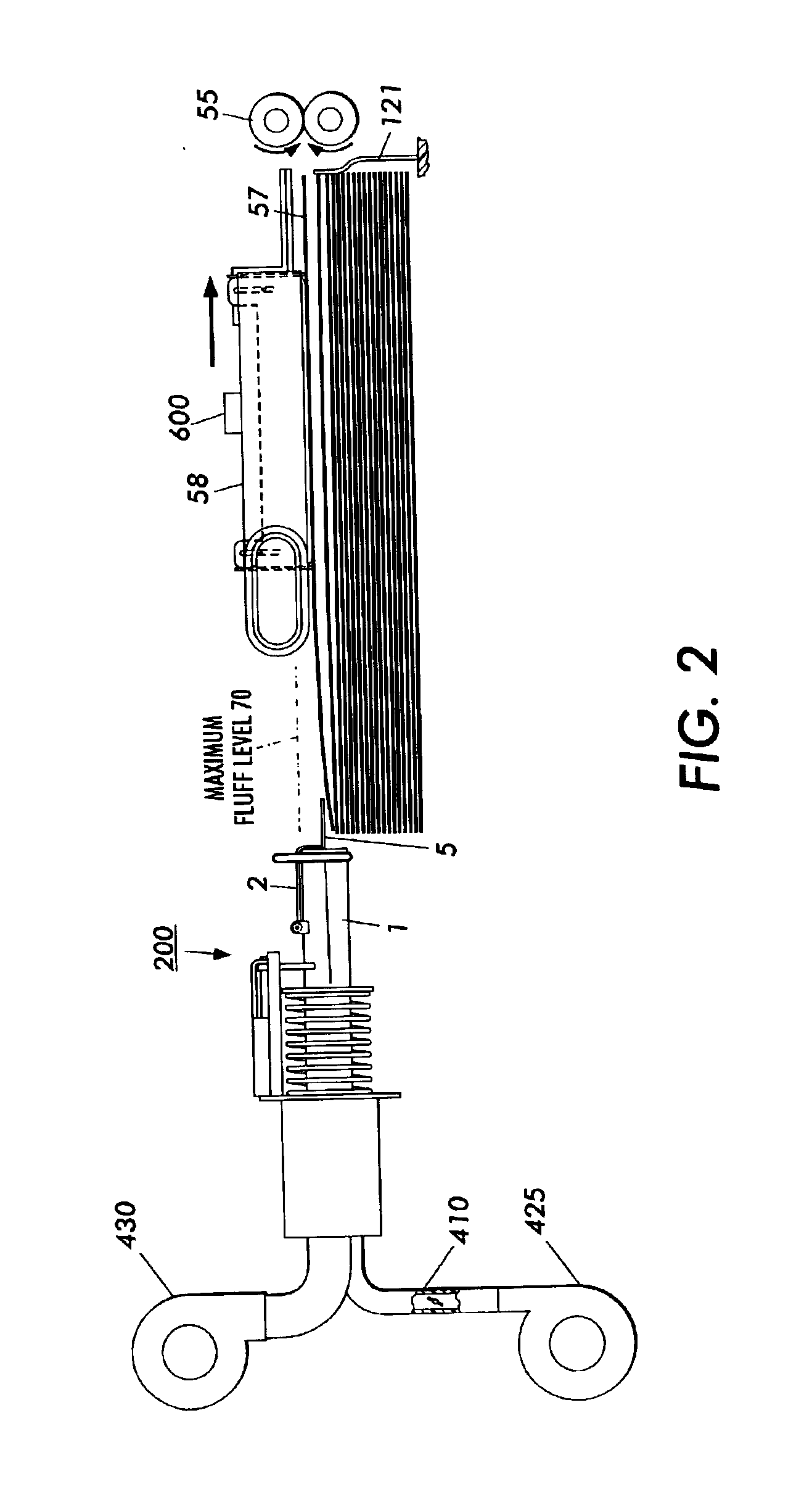
A sheet feeding apparatus for feeding a stack of sheets in a direction of movement to a process station, including: a sheet tray for holding the stack of sheets; an air plenum, positioned above the stack of sheets, for picking up a sheet from the stack of sheets when a vacuum force in the air plenum; a paper fluffer for blowing air between individual sheets in the stack, the paper fluffer having means for adjusting air flow between individual sheets.

Description

FIELD OF THE INVENTION[0001]This invention relates generally to an electronic reprographic printing system, and more particularly concerns feeder apparatus process for improving feeding of compilations of recording sheets that often accompanies this general method of reproduction and printing.BACKGROUND OF THE INVENTION[0002]In the process of electrostatographic reproduction, a light image of an original to be copied or printed is typically recorded in the form of a latent electrostatic image upon a photosensitive member, with a subsequent rendering of the latent image visible by the application of electroscopic marking particles, commonly referred to as toner. The visual toner image can be either fixed directly upon the photosensitive member or transferred from the member to another support medium, such as a sheet of plain paper. To render this toner image permanent, the image must be “fixed” or “fused” to the paper, generally by the application of heat and pressure.[0003]With the ...

Claims


Application Information

Patent Timeline
IPC IPC(8): B65H3/48B65H3/12
CPCB65H3/48B65H2515/342B65H2220/04B65H2220/02B65H2515/34
Inventor MATHEWSON, MARK D.
Owner XEROX CORP
Learn More