Knee protecting airbag device

an airbag device and knee protection technology, which is applied in the direction of process control, pedestrian/occupant safety arrangement, instruments, etc., can solve the problems of airbag devices not being mounted on the front side of the passenger sitting on the passenger seat, airbags may not receive the knees of the driver moving relatively forward, and the knees of the passenger may not be properly protected, etc., to achieve the effect of preventing the knee from falling off, and preventing the knee from falling

Inactive Publication Date: 2005-09-20
TOYODA GOSEI CO LTD
View PDF37 Cites 53 Cited by
  • Summary
  • Abstract
  • Description
  • Claims
  • Application Information

AI Technical Summary

Benefits of technology

[0019]A first object of the invention is to provide a knee protecting airbag device which can minimize the deviation of the upper end of an airbag leftward and rightward or rearward of the vehicle at the completion of the expansion and inflation of the airbag, even if the airbag is expanded and inflated while rising, thereby to protect the knees of the driver properly.

Problems solved by technology

If the deviation is larger, the airbag may fail to receive the knees of the driver moving relatively forward, properly.
This airbag device cannot be mounted on the front side of the passenger seated on the passenger's seat, because the column cover is not on the front side of that passenger.
However, a longer or shorter time difference usually occurs from the start of inflow of the inflating gas to the catch of the passenger's knees by the airbag.
If the upper end portion of the airbag falls down, moreover, the airbag cannot protect the knees of the passenger moving forward with the delay, properly.

Method used


Image

  • Knee protecting airbag device
  • Knee protecting airbag device
  • Knee protecting airbag device

Examples


first embodiment

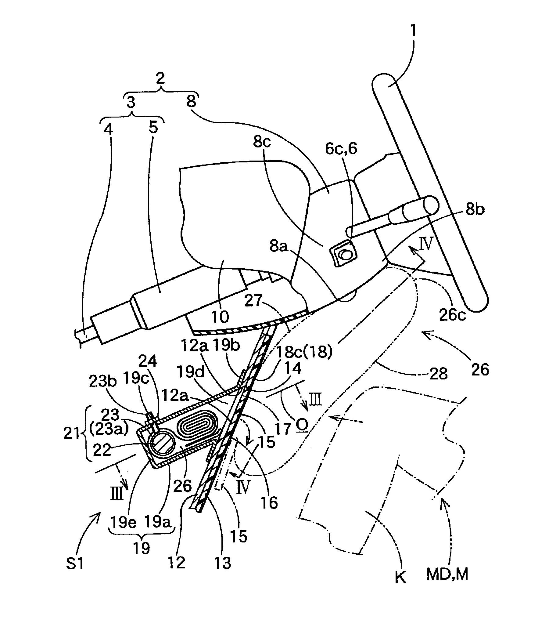
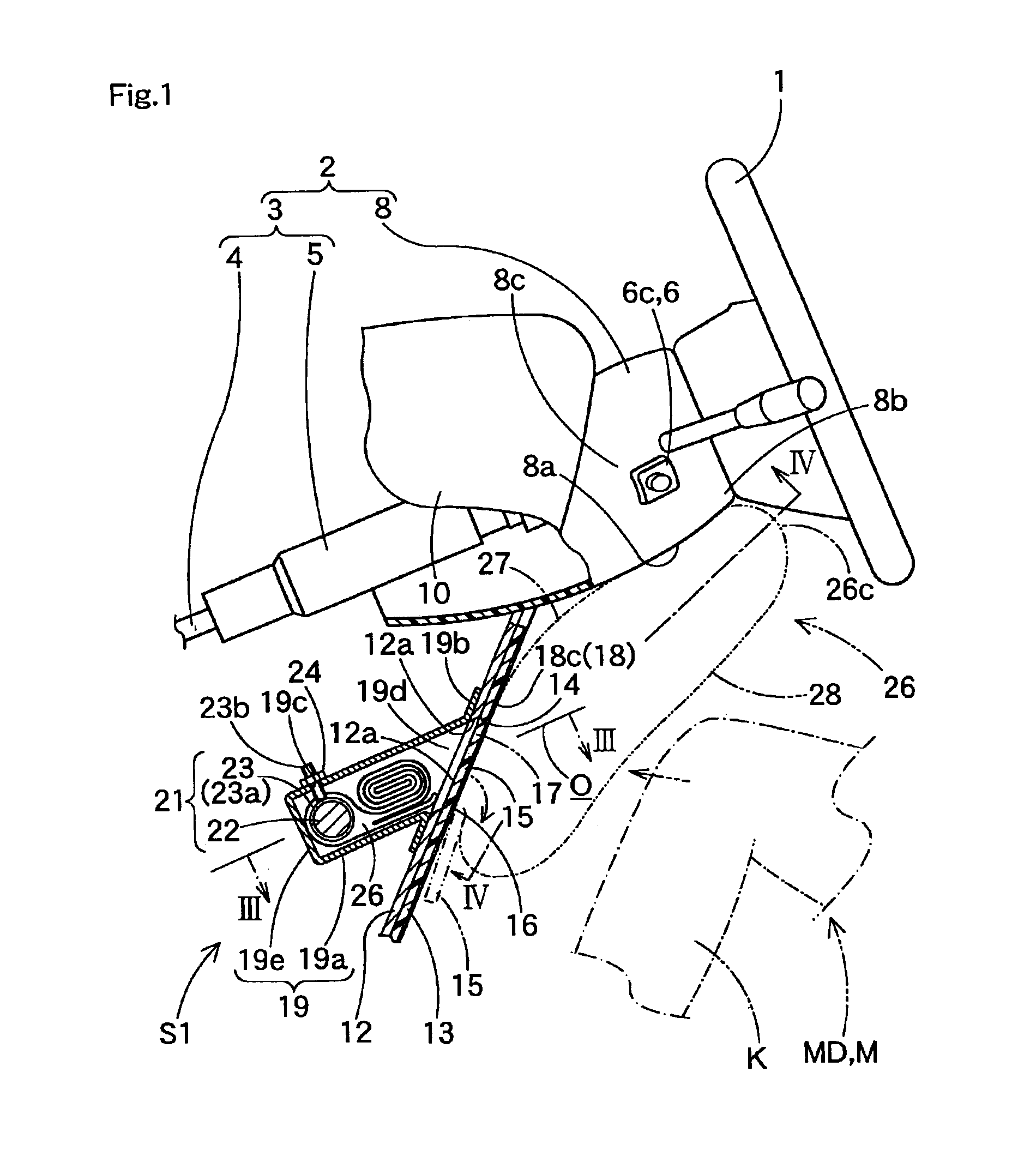
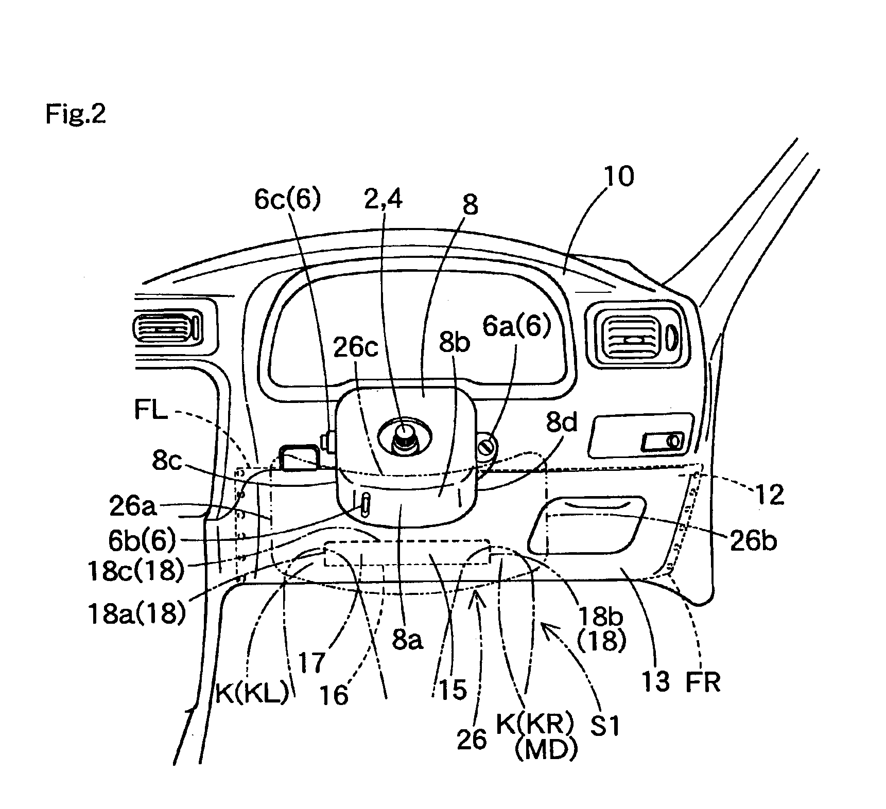
[0210]On the other hand, the column cover 8 is formed of a synthetic resin into a generally rectangular cylinder shape or the like. The column cover 8 is so arranged along the axial direction of the steering column 2 as to cover the steering column 2 below the steering wheel 1. Specifically, the column cover 8 is arranged with such a rearward rising inclination that its vehicular front side is arranged at a lower position whereas its vehicular rear side is arranged at a higher position. The lower face (or rear face) 8a of the column cover 8 is formed into a generally rectangular shape. Moreover, the lower face 8a of the column cover 8 is formed into a rearward rising curve in the longitudinal direction of the vehicle. Here in the case of the first embodiment, the column cover 8 is more protruded on the rear end side of its vehicular rear side rearward from an instrument panel (or dash board) 10, the holding member 12 or the airbag cover 13. On the lower edge side of the right side f...

second embodiment

[0268]The housing portion 117 is formed into a bottomed box shape having an opening 117a directed rearward of the vehicle. In the case of the second embodiment, the housing portion 117 is a formed into a generally rectangular parallelepiped box shape and is provided with a generally rectangular bottom wall portion 122 and a peripheral wall portion 118 having a generally rectangular cylinder shape. This peripheral wall portion 118 is arranged to enclose the opening 117a. In wall portions 118a and 118b of the peripheral wall portion 118 confronting each other transversely of the vehicle, there are individually arranged mounting holes 120 and 121 which are opened in larger and smaller circles for mounting the inflator 134. The mounting hole 120 is formed to insert thereinto the later-described column-shaped body portion 134a of the inflator 134. The mounting hole 120 can support the outer periphery of the body portion 134a in its inner periphery. The mounting hole 121 is given such an ...

fifth embodiment

[0323]Moreover, the tethers to be arranged in the airbag may be constructed into those of an airbag 140C of a knee protecting airbag device S5 as shown in FIGS. 24 to 28.

[0324]This airbag 140C takes, when completely expanded and inflated, a generally home base sheet shape similar to that of the airbag 140 of the second embodiment, as shown in FIGS. 25 and 26. Specifically, the airbag 140C is provided with the passenger side wall portion 141 and the body side wall portion 142 which have generally identical flat shapes. The passenger side wall portion 141 is arranged on the side of the driver MD when completely inflated. The body side wall portion 142 is arranged on the side of the body side column cover 8 when completely inflated. Moreover, the airbag 140C is constructed as a flat airbag by sewing the outer peripheral edges of the passenger side wall portion 141 and the body side wall portion 142 to each other. Here, the passenger side wall portion 141 and the body side wall portion...


PUM


Abstract

In a knee protecting airbag device of the present invention, an airbag is folded and housed on the front side of the knees of a seated passenger. The airbag is protruded rearward of a vehicle from a protruding opening and expanded and inflated upward, when an inflating gas flows in. And, the airbag is arranged on the front side of the knees of the passenger between a member on the body side and the knees of the passenger thereby to protect the knees of the passenger. The protruding opening has a transverse width size set within a range of ⅛ to ⅔ of the transverse width size of the airbag having completed its expansion and inflation.

Description

[0001]The present application claims priority to Japanese patent application of Takimoto et al., filed Nov. 9, 2001, No. 2001-345315, and Japanese patent application of Takimoto et al., filed Dec. 5, 2001, No. 2001-371899, and Japanese patent application of Mizuno et al., filed Dec. 25, 2001, No. 2001-392378, and Japanese patent application of Mizuno et al., filed Jan. 31, 2002, No. 2002-024547, and Japanese patent application of Takimoto et al., filed Apr. 24, 2002, No. 2002-122926, and Japanese patent application of Takimoto et al., filed Jun. 11, 2002, No. 2002-170130, the entirely of each is hereby incorporated into the present application by this reference.BACKGROUND OF THE INVENTION[0002]1. Field of the Invention[0003]The present invention relates to a knee protecting airbag device in which an airbag to be expanded and inflated by admitting an inflating gas can protect the knees of a passenger such as a driver or a person seated on a passenger's seat.[0004]2. Description of th...

Claims


Application Information

Patent Timeline
Patent Type & Authority Patents(United States)
IPC IPC(8): B60R21/16B60R21/20B60R21/00B60R21/26B60R21/205B60R21/2165B60R21/217B60R21/231B60R21/233B60R21/2338B60R21/2342B60R21/235B60R21/237B60R21/261
CPCB60R21/206B60R21/233B60R21/2338B60R21/237B60R21/261B60R21/2165B60R21/2171B60R21/2342B60R2021/0051B60R2021/161B60R2021/23169B60R2021/23382B60R2021/23547B60R2021/23595
Inventor TAKIMOTO, MASAHIROMIZUNO, YOSHIOKOYAMA, TORUSUZUKI, KAZUMASANAGATA, ATSUSHI
Owner TOYODA GOSEI CO LTD
Why Eureka
Try Eureka