Wind power plant having a power generation redundancy system

a power generation and redundancy system technology, applied in the direction of motors, dynamo-electric machines, single network parallel feeding arrangements, etc., can solve the problems of no longer generating or delivering electrical power, no way certain, and allowing immediate repair, so as to avoid overloading

Inactive Publication Date: 2005-09-20
WOBBEN ALOYS
View PDF14 Cites 32 Cited by
  • Summary
  • Abstract
  • Description
  • Claims
  • Application Information

AI Technical Summary

Benefits of technology

[0019]In a particularly preferred feature control of the switch devices is effected having regard to the output power to be switched, so that only one switch device switches when the level of output

Problems solved by technology

A disadvantage with that wind power installation however is that, in the event of failure of the generator and/or the transformer, the wind power installation can no longer generate or deliver any electrical power.
Even if it is possible to reach the installation however, it is in no way certain in that respect that the sea swell and the weather will permit immediate repair.
It will be seen therefore that, if the swell is high or if the weather is bad, such as for example if there is a storm, it is d

Method used


Image

  • Wind power plant having a power generation redundancy system
  • Wind power plant having a power generation redundancy system
  • Wind power plant having a power generation redundancy system

Examples


second embodiment

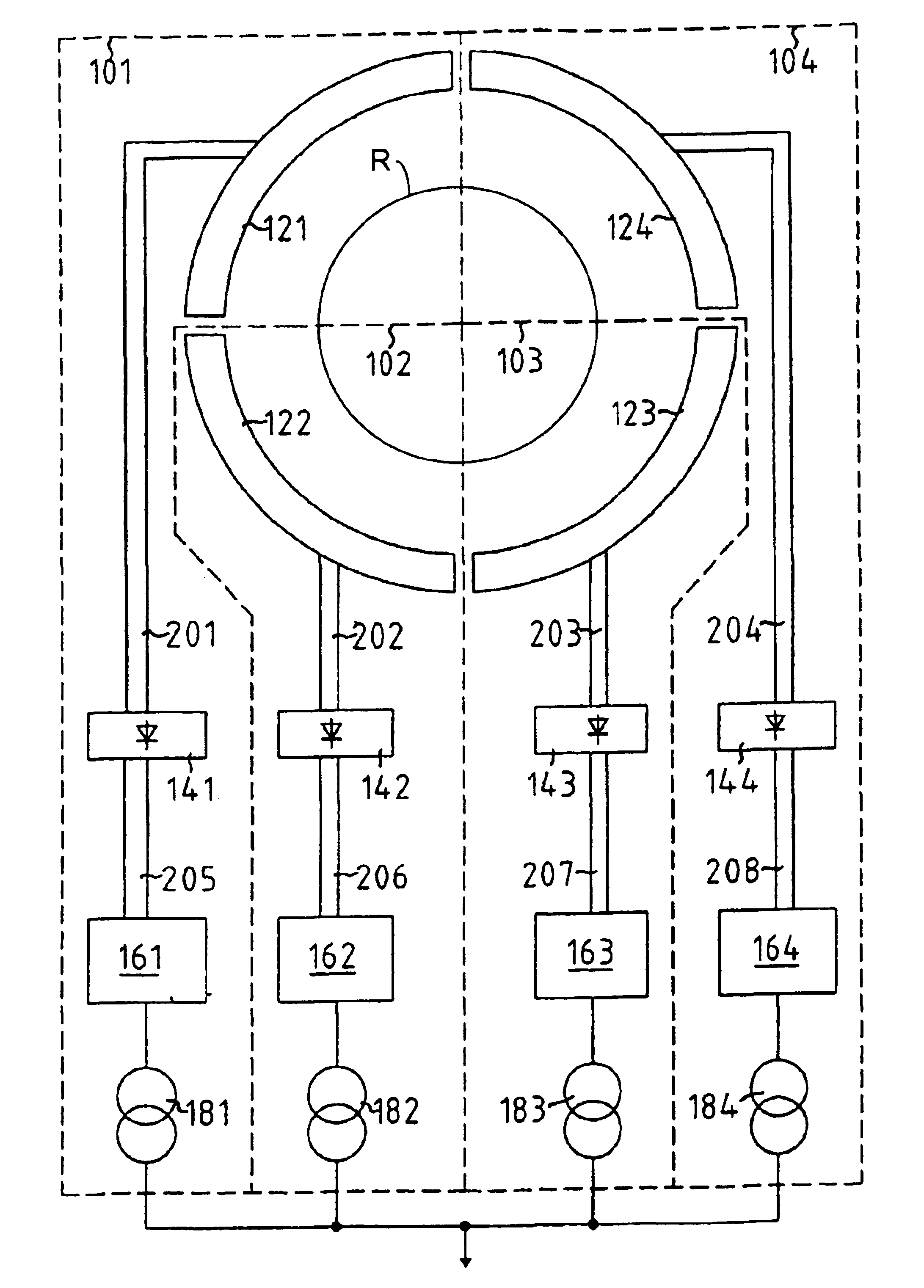
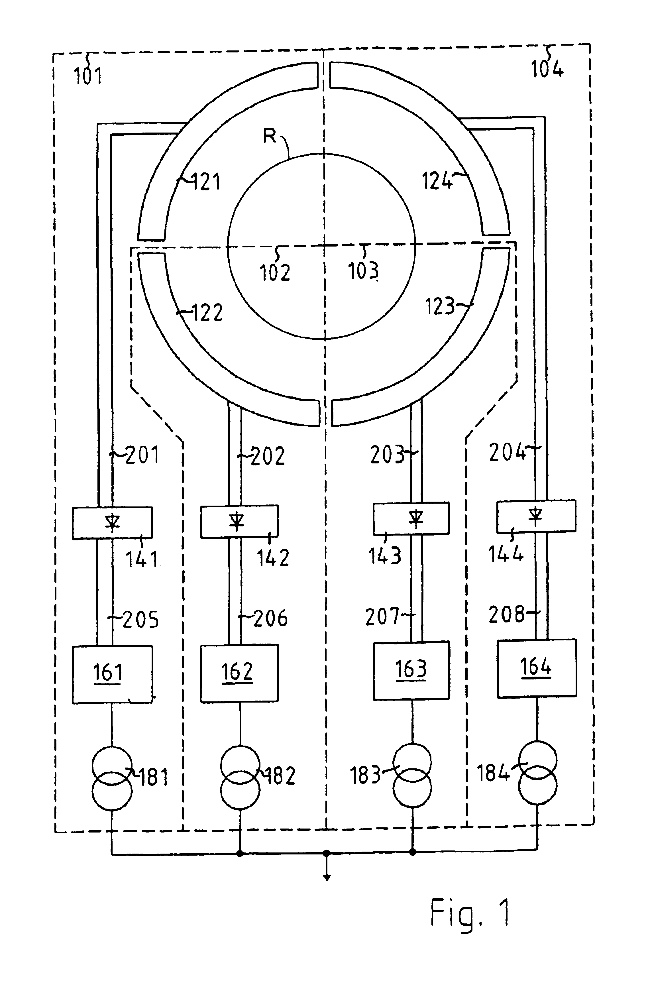
[0072]FIG. 6 shows the present invention. This embodiment corresponds in large parts thereof to the embodiment shown in FIG. 2 and differs therefrom by virtue of the saving on the switch devices 130, 131, 132, 150, 151, 152, 170, 171, 172 in FIG. 2 between each two components, so that the similar components of the individual systems 101, 102, 103, 104 in FIG. 1 are connected in parallel and accordingly in normal operation are all acted upon by approximately a quarter of the output power produced.

first embodiment

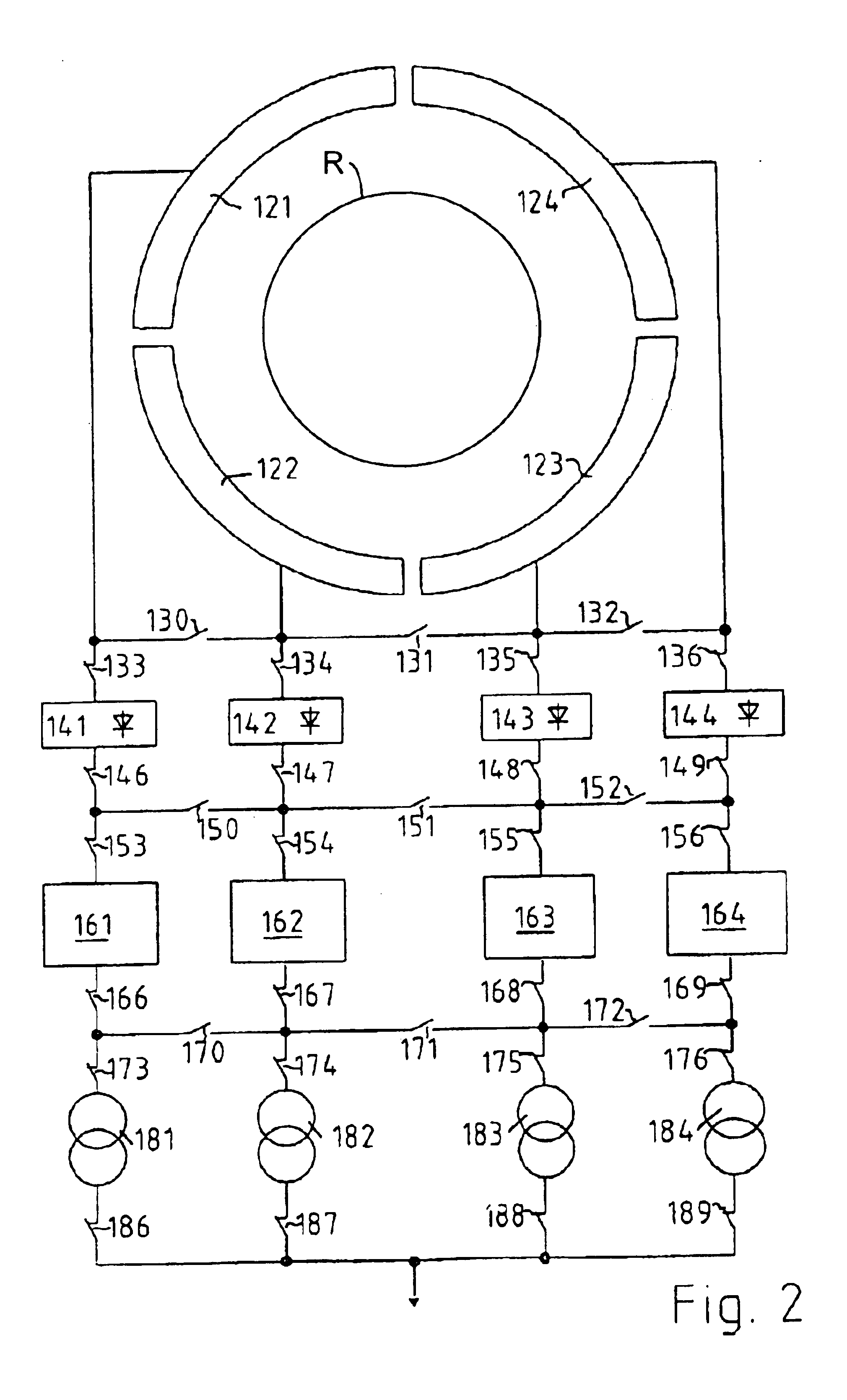
[0073]In a manner corresponding to the arrangement in the first embodiment the switch devices 133, 134, 135, 136, 146, 147, 148, 149, 153, 154, 155, 156, 166, 167, 168, 169, 173, 174, 175, 176, 186, 187, 188, 189 are closed in normal operation so that all systems 101, 102, 103, 104 are operating.

[0074]If now a fault occurs at a component that component is disconnected by opening of the switch devices 133, 146; 134, 147; 135, 148; 136, 149; 153, 166; 154, 167; 155, 168; 156, 169; 173, 186; 174, 187; 175, 188; 176, 189 arranged in the feed line and the out line of the component in question, and the other components in the other systems 101, 102, 103, 104 (FIG. 1) are automatically acted upon with a higher level of output power.

[0075]This can also be clearly seen once again from FIG. 7 in which the transformers 181, 182, 183, 184 are connected in parallel by the normally closed switch devices 173, 174, 175, 176, 186, 187, 188, 189. If now a transformer 181, 182, 183, 184 is found to be...


PUM


Abstract

A wind power installation having external and/or internal redundancy derived by multiple, independent power generating systems arranged in parallel, but switchably interconnected to allow substantial continued operation in the event of a critical component failure.

Description

BACKGROUND OF THE INVENTION[0001]The present invention concerns a wind power installation with preferably at least rectifiers and two inverters.[0002]Such a wind power installation is known from patent specification DE 196 20 906.4. A disadvantage with that wind power installation however is that, in the event of failure of the generator and / or the transformer, the wind power installation can no longer generate or deliver any electrical power. In the event of failure of a rectifier and / or an inverter it is still approximately half of the possible power yield that is lost at any event, so that rapid repair is required in order to limit at least the economic damage to the operator of the installation due to the energy yield which is lost.[0003]That known wind power installation has two phase-displaced stator windings which are arranged jointly on the same stator. The windings however are electrically insulated from each other and have a phase angle of 30° relative to each other. In th...

Claims


Application Information

Patent Timeline
IPC IPC(8): F03D9/00F03D7/02F03D7/00H02K7/18H02J3/00H02K16/04H02K16/00
CPCF03D7/0272F03D9/002H02K16/04H02J3/386Y02E10/723Y02E10/725Y02E10/763H02K7/1838F03D9/25H02J2300/28H02J3/381Y02E10/72Y02E10/76H02J3/46
Inventor WOBBEN, ALOYS
Owner WOBBEN ALOYS
Why Eureka
Try Eureka