Microstrip patch antenna and array antenna using superstrate

a dielectric superstrate and patch antenna technology, applied in the direction of resonant antennas, individually energised antenna arrays, protective materials radiating elements, etc., can solve the problems of narrow bandwidth, low antenna gain, disadvantages of microstrip antennas, etc., and achieve the effect of enhancing antenna gain

Inactive Publication Date: 2005-09-20
UNILOC 2017 LLC
View PDF5 Cites 48 Cited by
  • Summary
  • Abstract
  • Description
  • Claims
  • Application Information

AI Technical Summary

Benefits of technology

[0018]Therefore, it is an object of the present invention to provide a microstrip patch antenna using a dielectric superstrate in order to enhance the antenna gain by stacking radiating patches and dielectric layers.

Problems solved by technology

However, the microstrip antennas have disadvantages such as narrow bandwidth and low antenna gain.
However, a structure of the typical microstrip patch antenna does not provide broadband impedance characteristics.
Despite of increase in the number of radiating patches, it is difficult to obtain a high gain microstrip antenna because of large feeding loss.
However, the microstrip antenna of FIGS. 2A and 2B has a problem such as a narrow impedance bandwidth because a radiating patch is on a single layer substrate and it is not adequate to make an array antenna by using the microstrip antenna of FIGS. 2A because the radiating patch is fed to the coaxial cable.
Although the stacked layers of the microstrip patch antenna is proper to enhance impedance bandwidth characteristics, the antenna gain is not high enough to meet the requirement of the current needs such as a wireless communication base station, a wireless local area network, satellite communications and satellite broadcasting.

Method used


Image

  • Microstrip patch antenna and array antenna using superstrate
  • Microstrip patch antenna and array antenna using superstrate
  • Microstrip patch antenna and array antenna using superstrate

Examples


Embodiment Construction

[0031]Hereinafter, one embodiment of the present invention and measurement results will be described in detail with reference to the accompanying drawings.

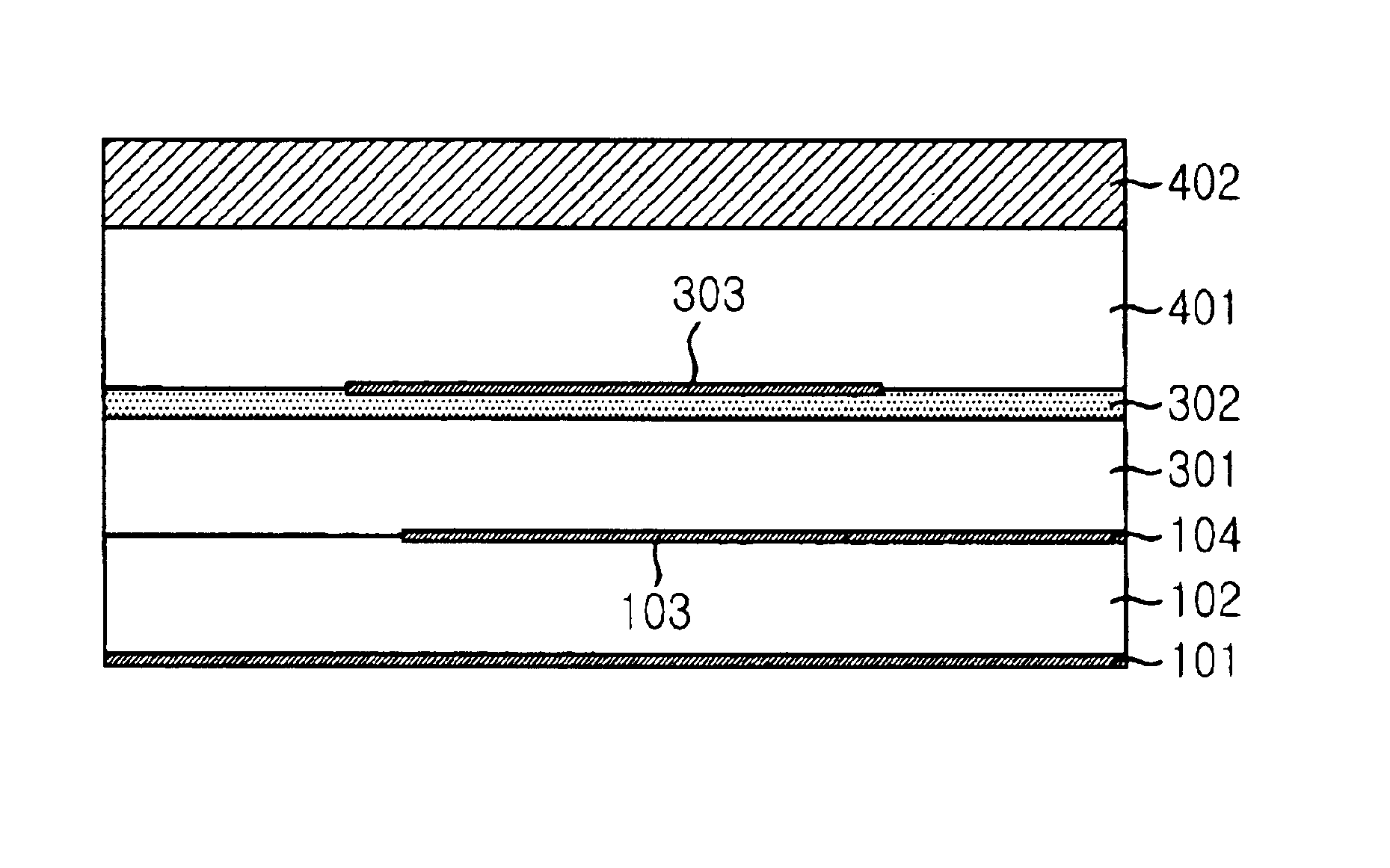
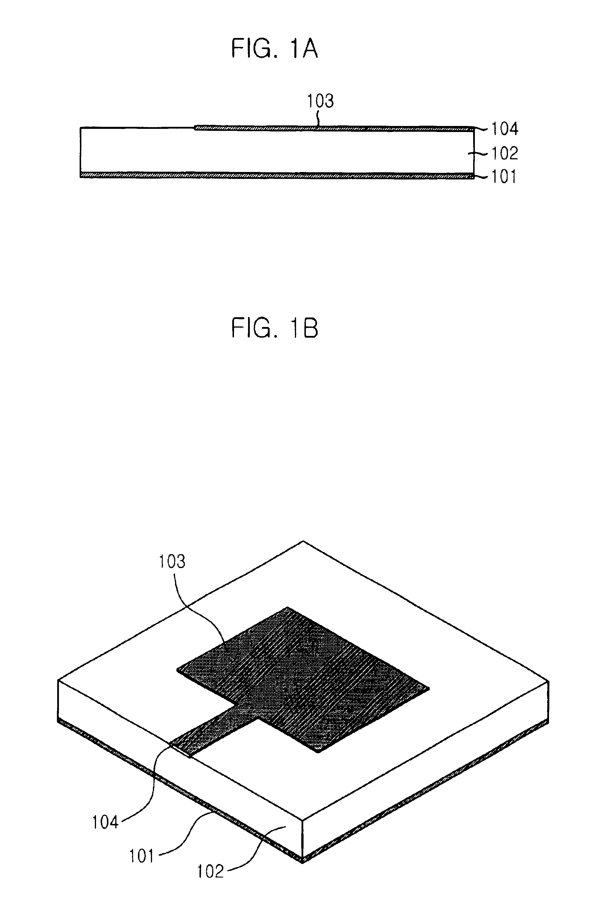
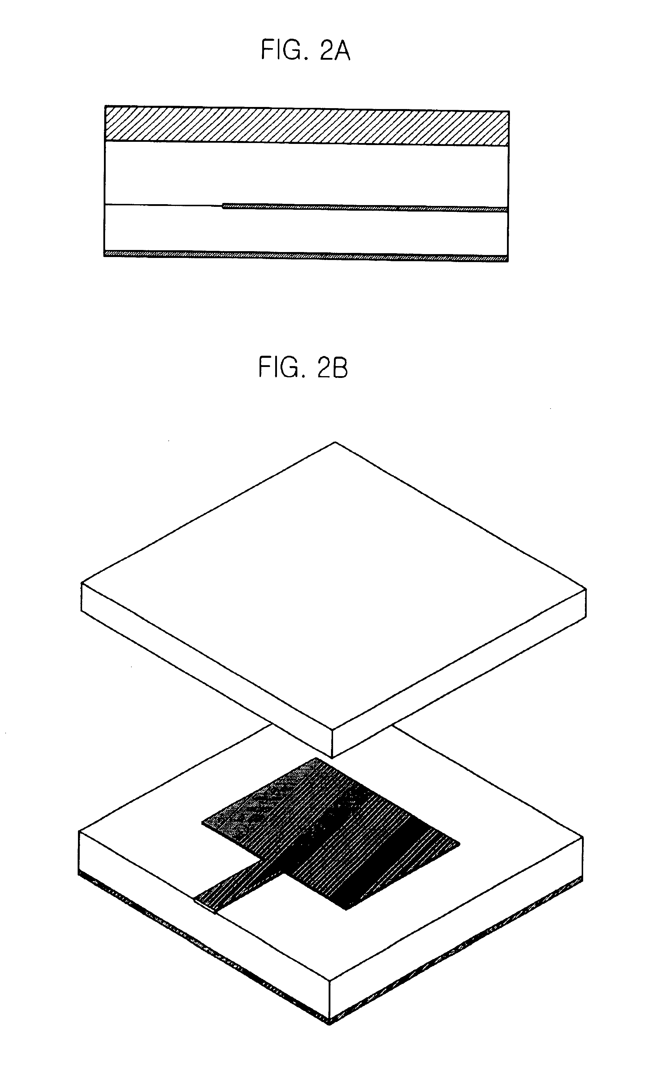
[0032]FIGS. 4A and 4B are a cross-sectional view and a perspective view of a microstrip patch antenna in accordance with the present invention.

[0033]Referring to FIGS. 4A and 4B, a dielectric layer 102 is formed on a ground plane 101, and a feedline 104 and a lower radiating patch 103 are formed on the dielectric layer 102 in the microstrip patch antenna in accordance with the present invention. The feedline 104 is electrically connected to the lower radiating patch 103.

[0034]A foam layer 301 is formed on the feedline 104 and the lower radiating patch 103, a dielectric film 302 is formed on the foam layer 301, and an upper radiating patch 303 is placed on the dielectric film 302.

[0035]An airgap 401 having a predetermined thickness is placed on the upper radiating patch 303 and a high permittivity dielectric superstrate 402 having ...


PUM


Abstract

The present invention provides a microstrip patch antenna and array antenna using dielectric superstrate in order to enhance the antenna gain by stacking radiating patches and dielectric layers. The microstrip patch antenna using a dielectric superstrate for having high gain and wide bandwidth, includes: a lower patch antenna layer having a dielectric layer and a ground plane for radiating energy by exciting current by a feedline; a upper patch antenna layer having dielectric film electromagnetically coupled by the lower radiating patch; a foam layer for distancing the upper patch antenna layer from the lower patch antenna layer; and a dielectric superstrate located by being predeteremined distant from the upper patch antenna layer.

Description

FIELD OF THE INVENTION[0001]The present invention relates to a microstrip patch antenna and array antenna using a dielectric superstrate, and particularly to a microstrip patch antenna using a dielectric superstrate and an array antenna using the same, for a wireless communication base station, a wireless local area network, satellite communications and satellite broadcasting.DESCRIPTION OF THE PRIOR ART[0002]The concept of microstrip radiators was first proposed by Deschamps as early as 1953. There are many advantages and disadvantages of microstrip antennas compared with other microwave antennas. The advantages include lightweight, low volume, low profile planar configurations and low fabrication cost. However, the microstrip antennas have disadvantages such as narrow bandwidth and low antenna gain.[0003]FIGS. 1A and 1B are a cross-sectional view and a perspective view of a typical microstrip patch antenna.[0004]As shown in FIGS. 1A and 1B, a typical microstrip patch antenna has a...

Claims


Application Information

Patent Timeline
Patent Type & Authority Patents(United States)
IPC IPC(8): H01Q1/00H01Q19/06H01Q1/40H01Q9/04H01Q19/00H01Q21/06H01Q21/00
CPCH01Q1/40H01Q9/0414H01Q19/062H01Q21/065H01Q21/00
Inventor CHOI, WON KYUCHEOL, SIG PYOLEE, JONG MOONYOON, YOUNG KEUNCHO, YONG HEUICHAE, JONG-SUKCHOI, JAE ICK
Owner UNILOC 2017 LLC
Why Eureka
Try Eureka