Antenna structure

a technology of antenna and structure, applied in the direction of radiating element structure, resonant antenna, substantially flat resonant elements, etc., can solve the problems of inability to improve the efficacy of antenna gain and suffer from antenna signal quality, so as to increase the bandwidth, increase the antenna gain, and improve the effect of antenna gain

Inactive Publication Date: 2014-01-21
ADVANCED CONNECTION TECH
View PDF10 Cites 2 Cited by
  • Summary
  • Abstract
  • Description
  • Claims
  • Application Information

AI Technical Summary

Benefits of technology

[0009]Accordingly, the present invention is directed to an antenna structure so as to enhance the antenna gain and increase the bandwidth or provide multiple modes. The present invention is further directed to an antenna structure so as to enable an electronic device to have pleasing housing without reducing the gain of the antenna when being applied in the electronic device.

Problems solved by technology

Due to the shielding effect of metal, the delivery of electromagnetic waves is blocked, and antenna signal quality suffers.
However, the metal sheet 24a must avoid being overlapped excessively with the antenna 26a, otherwise it is not possible to improve the efficacy of antenna gain, and the shielding effect described above will result.

Method used


Image

  • Antenna structure
  • Antenna structure
  • Antenna structure

Examples


first embodiment

[0031]FIG. 5 is a gain comparison view of the first embodiment, in which comparison is performed on the gain charts of only a radiation unit 14 and a radiation unit 14 in cooperation with a metal plate without a hole. It can be seen that although in the frequency bands of 2 GHz-4 GHz, 2.2 GHz-2.9 GHz, and 3.6 GHz-4 GHz, the metal plate without a hole is helpful to increase the gain, in the frequency band of 2.9 GHz-3.6 GHz, the gain is reduced significantly. However, the antenna structure 1 of the present invention can improve the gain significantly in the frequency band of 2 GHz-4 GHz. It can be seen that the antenna structure 1 of the present invention actually has good communication capability.

[0032]FIG. 6 is a return loss comparison view of the first embodiment of the present invention, in which a comparison is performed on the gain charts of the radiation unit 14 and the radiation unit 14 in cooperation with a metal plate without a hole. It can be seen that, although the metal ...

third embodiment

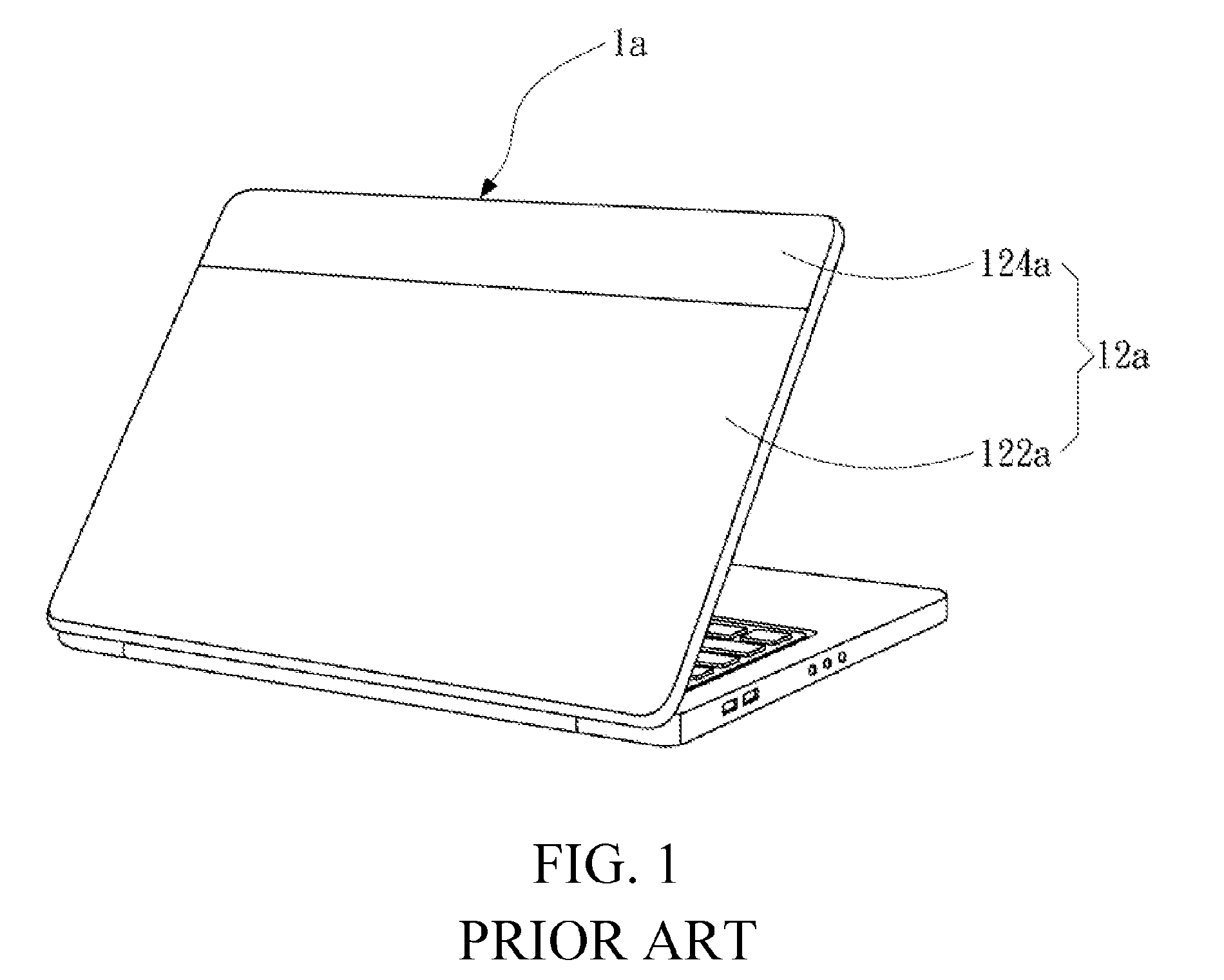
[0036]FIG. 8 is a schematic view of the present invention. A notebook computer 2 is taken as an example to illustrate how to apply the antenna structure of the present invention. The metal plate 16 may be a part of a back housing 22 of the notebook computer 2. The material of the back housing 22 may be plastic, carbon fiber, or magnalium, and the metal plate 16 may be connected to the back housing 22 in an embedding manner. A radiation unit (not shown), of the notebook computer 2 is generally disposed inside the back housing 22 above the screen, and the metal plate 16 is disposed above the radiation unit and is combined with the back housing 22, such that the gain of the radiation unit is improved, and a desired figure of the product is obtained. Here, the metal plate 16 and the back housing 22 may also be formed integrally.

[0037]FIGS. 9 and 10 are respectively a schematic view and a side view of a fourth embodiment of the present invention. Please refer to FIGS. 9 and 10, in which ...


PUM


Abstract

An antenna structure includes a substrate, a radiation unit, and a metal plate. The radiation unit is disposed on the substrate. The metal plate is separated from the radiation unit for a distance and is electrically isolated with the radiation unit. The metal plate is excited by the radiation unit to generate at least one resonance mode, and includes a hole penetrating the metal plate. Thus, the gain is enhanced, the bandwidth is increased, and multiple resonance modes are provided.

Description

CROSS-REFERENCES TO RELATED APPLICATIONS[0001]This non-provisional application claims priority under 35 U.S.C. §119(a) on Patent Application No. 99128443 filed in Taiwan, R.O.C. on 2010 Aug. 25, the entire contents of which are hereby incorporated by reference.BACKGROUND OF THE INVENTION[0002]1. Technical Field[0003]The present invention relates to an antenna structure, and more particularly to an antenna structure capable of enhancing the radiation effect of the entire antenna.[0004]2. Related Art[0005]With the development of wireless communication technologies, many wireless communication devices, such as mobile phones, notebook computers, personal digital assistants (PDAs), GPS Satellite Navigation Systems, and E-book readers, have been developed. Aside from wireless communication functions, by replacing a conventional external antenna with an embedded antenna, the wireless communication devices can be built with an attractive, light, and thin industrial design while having a goo...

Claims


Application Information

Patent Timeline
Patent Type & Authority Patents(United States)
IPC IPC(8): H01Q1/38
CPCH01Q9/0407H01Q13/10H01Q1/2266
Inventor WANG, YANG-KAICHEN, CHIEN-HUNGYEH, SHU-ANLAI, YU-CHANG
Owner ADVANCED CONNECTION TECH
Why Eureka
Try Eureka