Multi-loop transformer having wideband frequency applications

a multi-loop transformer and wideband technology, applied in the field of transformers, can solve the problems of increasing power consumption and reducing gain, and achieve the effect of widening the bandwidth of the balun without reducing the q of the balun, without introducing additional losses, and without reducing gain

Active Publication Date: 2015-07-28
QUALCOMM INC
View PDF8 Cites 2 Cited by
  • Summary
  • Abstract
  • Description
  • Claims
  • Application Information

AI Technical Summary

Benefits of technology

[0007]A balun transformer is disclosed that may operate at wider bandwidths than similarly-sized conventional balun transformers without introducing any losses or other performance degradations. In accordance with the present embodiments, a balun is disclosed that includes an input port, an output port, a main tank circuit, and at least one auxiliary tank circuit. The input port is to receive an input signal, and the output port is to provide an output signal generated in response to the input signal. The main tank circuit includes a primary winding coupled to the input port, and a secondary winding coupled to the output port. The auxiliary tank circuit includes an auxiliary winding magnetically coupled to the primary winding and to the secondary winding. The auxiliary winding is terminated in a termination capacitor coupled in parallel with the auxiliary winding. In this manner, the auxiliary tank circuit is electrically isolated from the main tank circuit and electrically isolated from the output port.
[0008]The main tank circuit is to resonate at a first frequency and has a first frequency response. The auxiliary tank circuit is to resonate at a second frequency different from the first frequency, and has a second frequency response. The frequency responses of the main tank circuit and the auxiliary tank circuit may combine to result in a composite frequency response that is wider than the frequency response of the main tank circuit. In this manner, the addition of the auxiliary tank circuit(s) may widen the bandwidth of the balun without reducing the Q of the balun, and therefore without introducing additional losses and / or without reducing gain.

Problems solved by technology

Although effective in widening the frequency response of the balun, de-Q'ing the balun introduces unwanted losses, reduces gain, and may increase power consumption.

Method used


Image

  • Multi-loop transformer having wideband frequency applications
  • Multi-loop transformer having wideband frequency applications
  • Multi-loop transformer having wideband frequency applications

Examples


Embodiment Construction

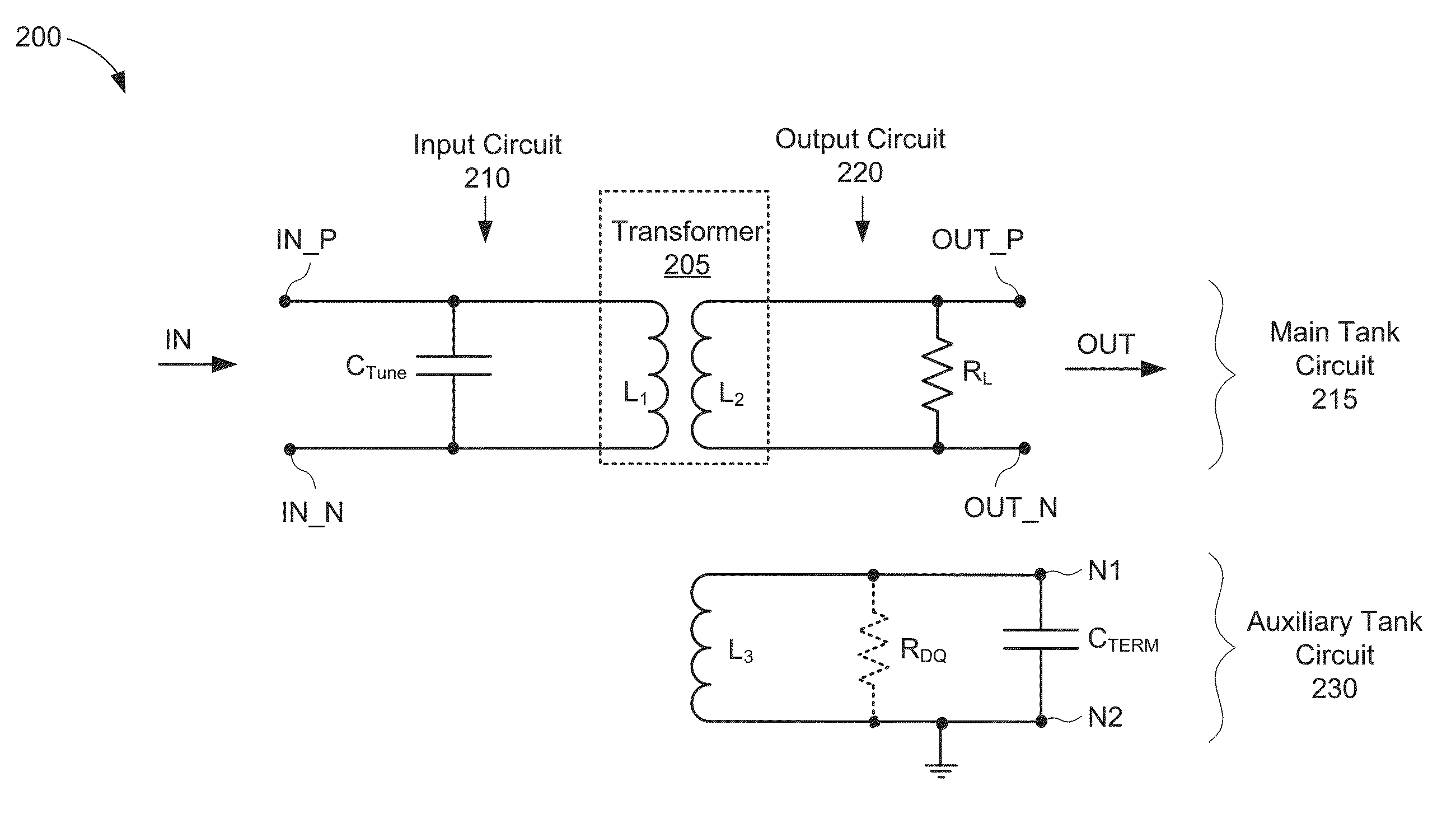
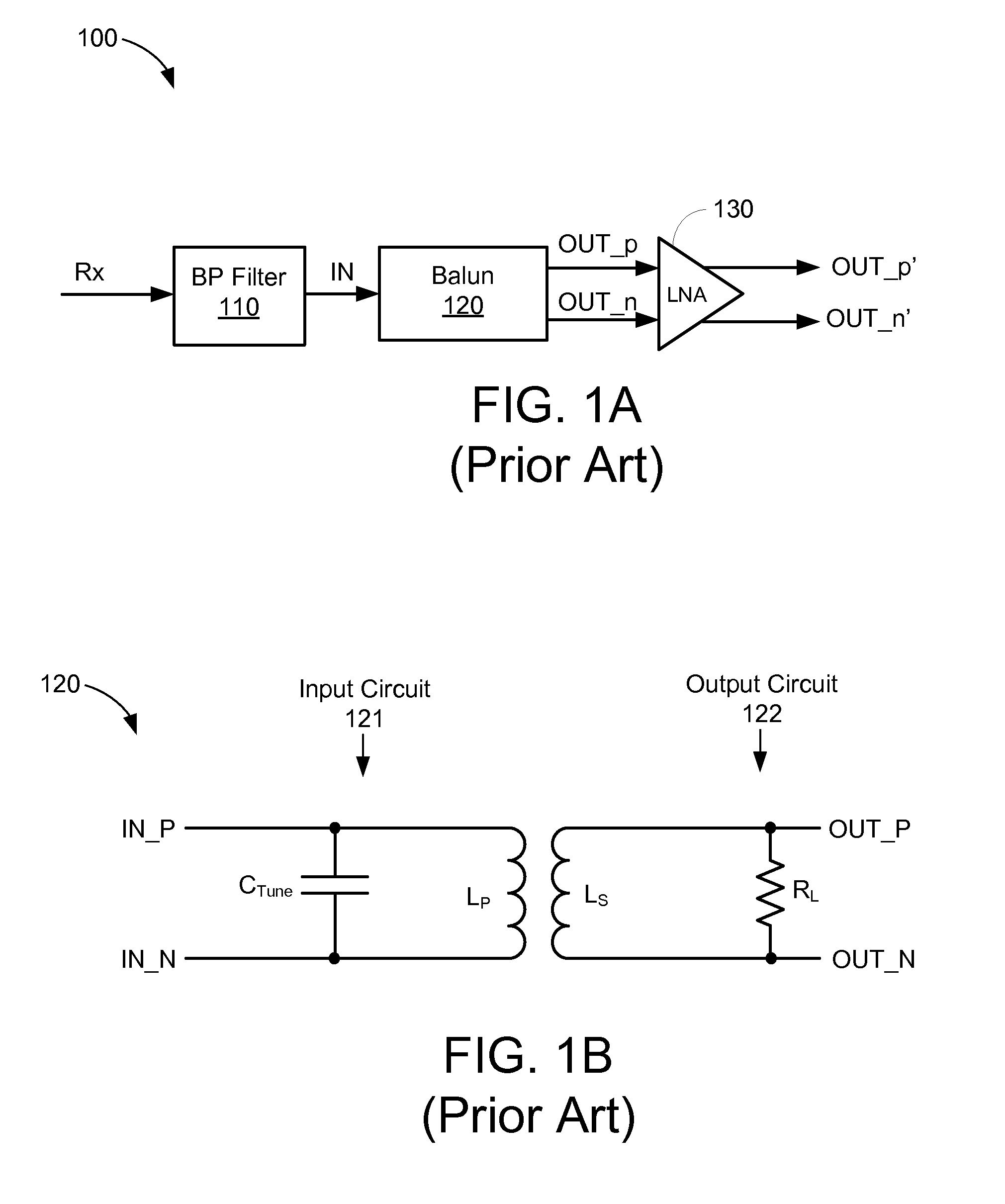
[0024]The present embodiments are described below in the context of balun transformers for simplicity only. It is to be understood that the present embodiments are equally applicable for other types of transformers, and / or for other devices that employ multiple resonant circuits. Further, although some embodiments may be discussed below in the context of front-end circuits employing low noise amplifiers, the present embodiments are equally applicable for front-end circuits employing other components such as, for example, variable-gain amplifiers, power amplifiers, filters, and mixers. In addition, the present embodiments may be employed within one or more low noise amplifiers, variable-gain amplifiers, power amplifiers, filters, and / or mixers. As used herein, the term “inductor” may refer to inductive elements formed by a wire, a coil, a winding, and / or conductive traces formed on a silicon chip. Thus, the terms “inductor,”“coil,” and “winding” may be used interchangeably herein. Fu...


PUM


Abstract

A balun is disclosed that includes a main tank circuit, and at least one auxiliary tank circuit. The main tank circuit includes a primary winding and a secondary winding. The auxiliary tank circuit, which includes an auxiliary winding magnetically coupled to the primary and secondary windings and terminated in a capacitor, is electrically isolated from the main tank circuit and from an output port of the balun. The frequency responses of the main tank circuit and the auxiliary tank circuit may combine to result in a composite frequency response that is wider than the frequency response of the main tank circuit. The auxiliary tank circuit may be formed within an interior area of the primary and secondary windings of the main tank circuit.

Description

TECHNICAL FIELD[0001]The present embodiments relate generally to transformers, and specifically to baluns having wide frequency bandwidths.BACKGROUND OF RELATED ART[0002]Many communication devices include a balanced-to-unbalanced (balun) transformer to transform differential signals into single-ended signals, and / or to transform single-ended signals into differential signals. A balun typically includes two mutually coupled inductors (e.g., coils or windings) configured such that an input signal applied to the primary inductor induces an output voltage across the secondary inductor. In addition to transforming signals, baluns may also be used to provide impedance matching and filtering functions.[0003]The quality factor (Q) of the balun may indicate the efficiency of energy transfer from the primary inductor to the secondary inductor. For example, a higher value of Q may indicate a higher voltage gain, higher energy transfer, and lower signal-to-noise ratio (SNR) for the balun, where...

Claims


Application Information

Patent Timeline
Patent Type & Authority Patents(United States)
IPC IPC(8): H03H5/00H03H7/42H01F27/28
CPCH03H7/42H01F27/2804H01F21/12
Inventor JOOYAIE, ALBORZMOLOUDI, SHERVIN
Owner QUALCOMM INC
Why Eureka
Try Eureka