Method of operating an oscilloscope

a technology of oscilloscope and operating method, which is applied in the direction of cathode-ray oscilloscope, noise figure or signal-to-noise ratio measurement, instruments, etc., can solve the problem that the acquisition rate of most digital storage oscilloscopes is rather low

Inactive Publication Date: 2005-09-20
TEKTRONIX INC
View PDF33 Cites 22 Cited by
  • Summary
  • Abstract
  • Description
  • Claims
  • Application Information

AI Technical Summary

Benefits of technology

[0008]In accordance with a second aspect of the invention there is provided an oscilloscope that is capable of displaying simultaneously multiple waveforms representing time evolution of a signal during respective acquisition intervals, said oscilloscope comprising an acquisition means for acquiring waveform data using a first set of acquisition parameters, a display means for generating a display based on the waveform data acquired by the acquisition means, a user control means that can be used in the event that the display generated by the display means includes a waveform that is visually distinct from other displayed waveforms to select a feature that distinguishes the visually distinct waveform from other displayed waveforms, and an oscilloscope control means for automatically deriving acquisition parameters that discriminate between the selected feature and other features of the displayed waveforms, and for supplying the derived acquisition parameters to the acquisition means, whereby the acquisition means can acquire waveform data using the derived acquisition parameters and the display means can generate a display based on the waveform data acquired by the acquisition means using the derived acquisition parameters.

Problems solved by technology

Until recently, most digital storage oscilloscopes had a rather low acquisition rate, such that a conventional digital storage oscilloscope might not display an infrequent event.

Method used


Image

  • Method of operating an oscilloscope
  • Method of operating an oscilloscope
  • Method of operating an oscilloscope

Examples


first embodiment

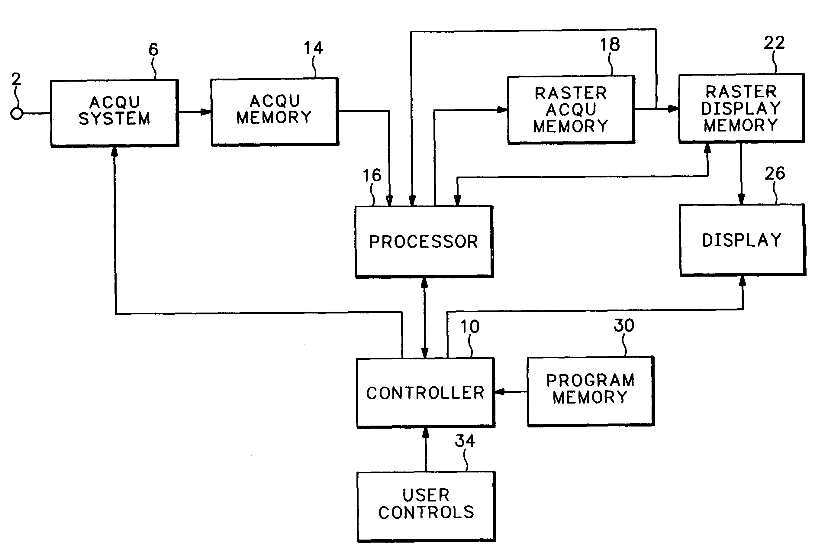
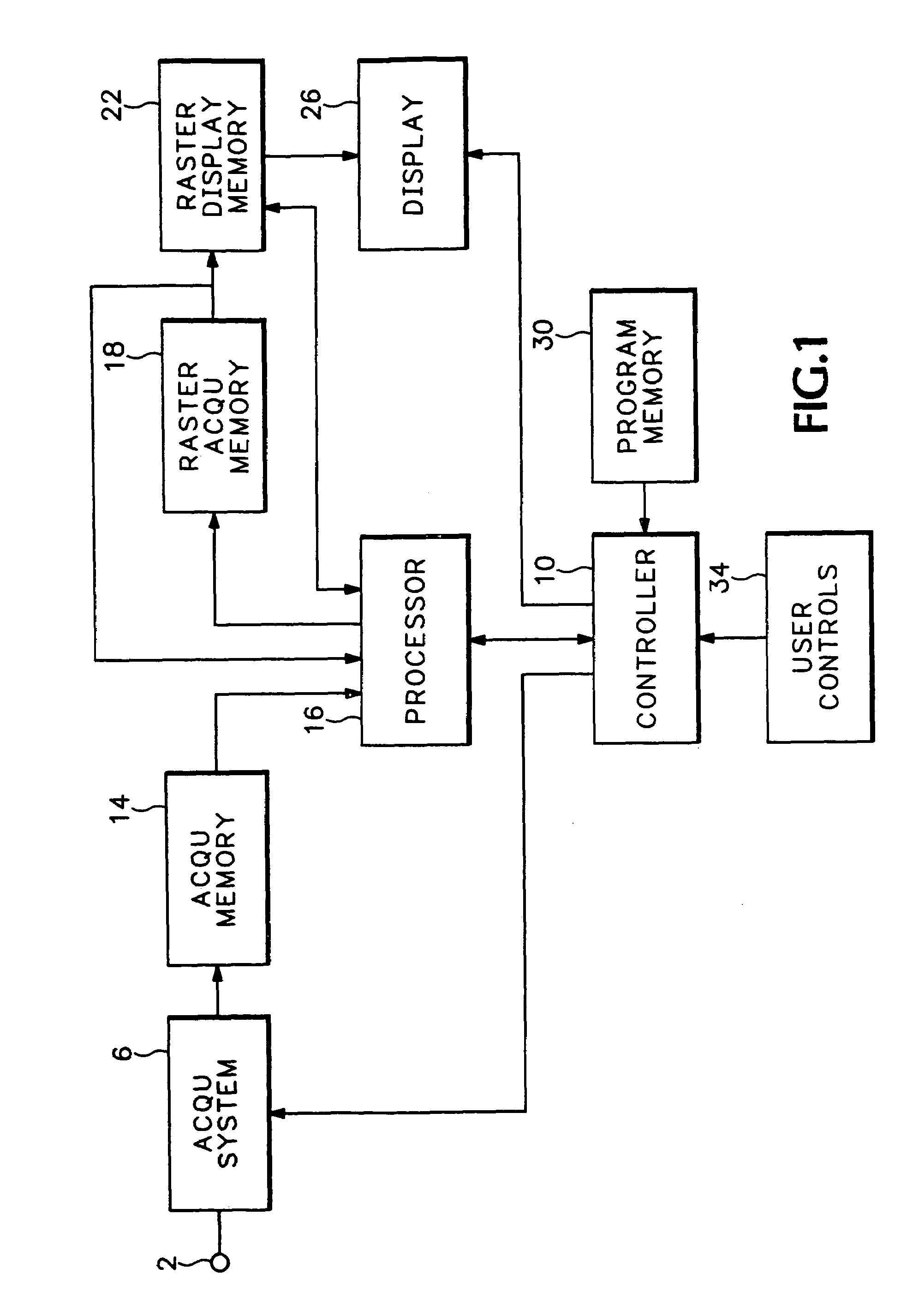
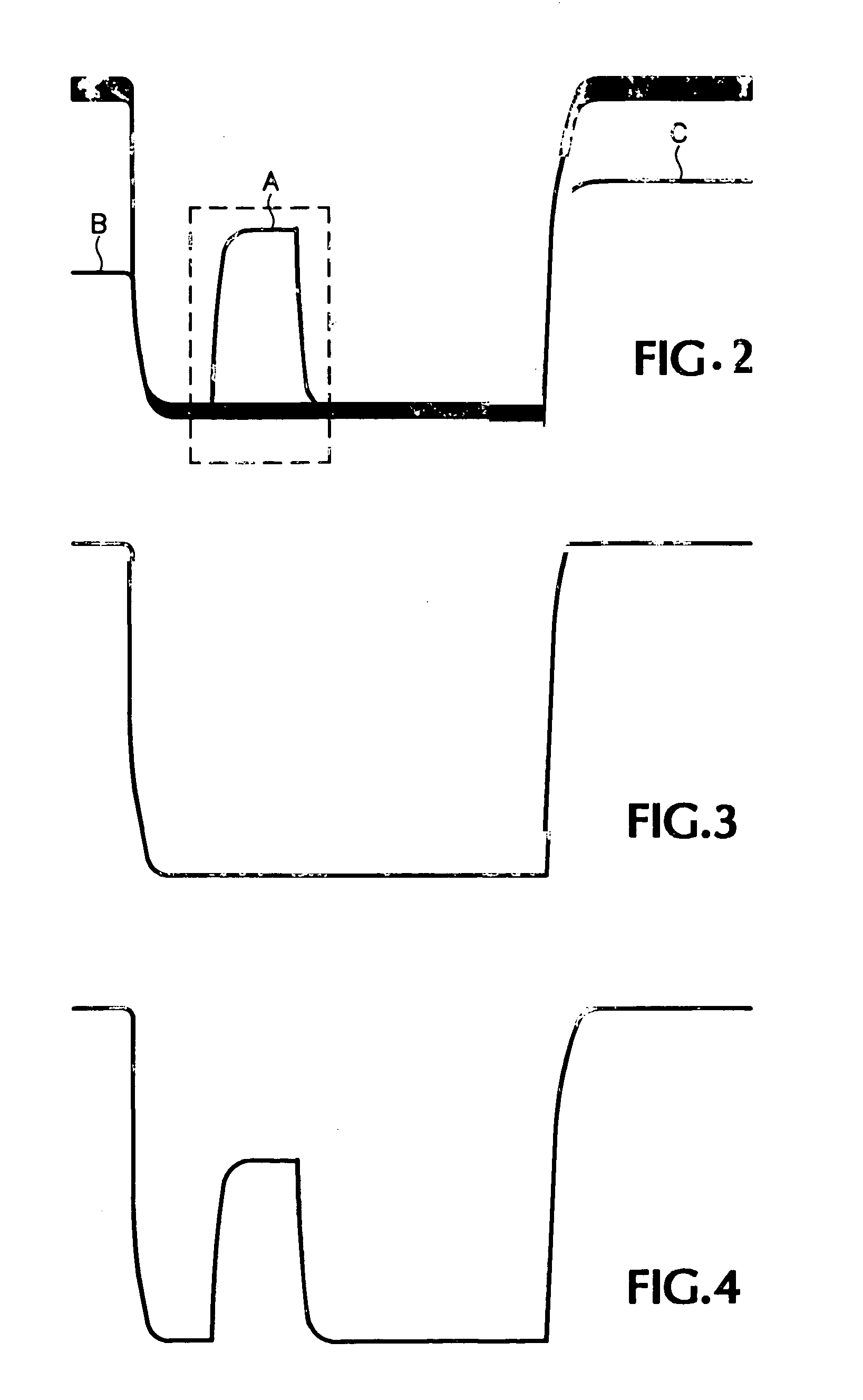
[0021]In accordance with the invention, the user employs the pointing device to define a scaleable rectangular box on the display screen. The technique for displaying such a scaleable rectangular box is well known. The user employs the pointing device to select a point on the display screen as an anchor for one corner of the box and to adjust selectively the size and aspect ratio of the box by dragging the diagonally opposite corner. The display controller modifies the display to include the box. The vertical dimension of the box represents a voltage range and the horizontal dimension of the box represents a time interval. The user adjusts the size and position of the rectangular box so that it surrounds the feature of interest. The vertical dimension of the box then represents a voltage range associated with the feature and the horizontal dimension of the box represents a time interval associated with the feature. The display controller supplies the coordinates of the corners of th...

third embodiment

[0028]In accordance with the invention, the user can select waveform features of the delay record and the main record and the processor can automatically qualify the acquisition parameters to refine the delay holdoff function so that only acquisitions that include selected infrequent events will be displayed.


PUM


Abstract

An oscilloscope that is capable of displaying simultaneously multiple waveforms representing time evolution of a signal during respective acquisition intervals acquires waveform data using a first set of acquisition parameters and generates a display based on that waveform data. If the display includes a waveform that is visually distinct from other displayed waveforms, the user selects a feature that distinguishes the visually distinct waveform from other displayed waveforms. The oscilloscope automatically derives updated acquisition parameters that discriminate between the selected feature and other features of the displayed waveforms. The oscilloscope then acquires waveform data using the updated acquisition parameters and generates a display based on that waveform data.

Description

BACKGROUND OF THE INVENTION[0001]This invention relates to a method of operating an oscilloscope.[0002]Until recently, most digital storage oscilloscopes had a rather low acquisition rate, such that a conventional digital storage oscilloscope might not display an infrequent event.[0003]The digital oscilloscope described in U.S. Pat. No. 5,986,637, the entire disclosure of which is hereby incorporated by reference herein for all purposes, has a very high acquisition rate which allows the user to view infrequent anomalies that might previously have been overlooked due to the low acquisition rate of a hitherto-conventional digital storage oscilloscope. After noticing an anomaly in the signal, the user might want to learn more about a potential problem that might be indicated by the signal and the user will accordingly want to adjust the acquisition parameters of the oscilloscope to trigger on the anomaly.[0004]Current digital storage oscilloscopes have the ability to trigger on a varie...

Claims


Application Information

Patent Timeline
Patent Type & Authority Patents(United States)
IPC IPC(8): G01R13/20G01R13/00G01R13/22G01R13/02G09G5/36G01R13/28G01R13/34
CPCG01R13/0236G01R13/28G01R13/345
Inventor KLINGMAN, KAYLA R.DAVIDSON, SCOTT A.
Owner TEKTRONIX INC
Why Eureka
Try Eureka