Reflector which appears bright when viewed at specific angle and reflective liquid crystal display

a technology of reflection liquid crystal display and reflector, which is applied in the direction of mirrors, non-linear optics, instruments, etc., can solve the problems of insufficient brightness, degrading visibility, and varying the brightness of the display surface, so as to achieve wide viewing angle range, suppress back reflection, and improve visibility

Inactive Publication Date: 2005-09-20
ALPS ALPINE CO LTD
View PDF17 Cites 55 Cited by
  • Summary
  • Abstract
  • Description
  • Claims
  • Application Information

AI Technical Summary

Benefits of technology

[0041]In addition, in a reflective liquid crystal display containing the reflector of the present invention, display surface appears especially ...

Problems solved by technology

Accordingly, when the display surface is observed, there are problems in that the brightness of the display surface varies depending on the positional relationship between the light source and the viewpoint and visibility is degraded due to back reflection, that is, reflection of the light source, the observer's face, etc., in the display surface.
Thus, there is a problem in that sufficient brightness cannot be obtained when the display surface is observed in a specific vi...

Method used


Image

  • Reflector which appears bright when viewed at specific angle and reflective liquid crystal display
  • Reflector which appears bright when viewed at specific angle and reflective liquid crystal display
  • Reflector which appears bright when viewed at specific angle and reflective liquid crystal display

Examples


Embodiment Construction

[0053]An embodiment of the present invention will be described below with reference to the accompanying drawings; however, it is not intended to limit the scope of the present invention.

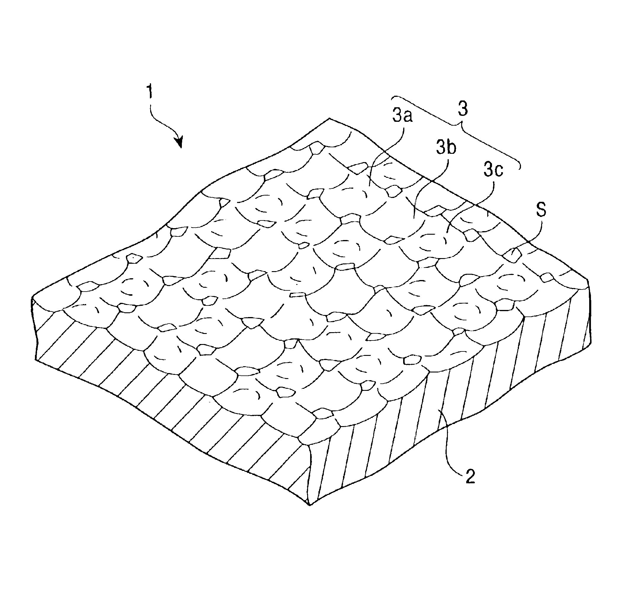
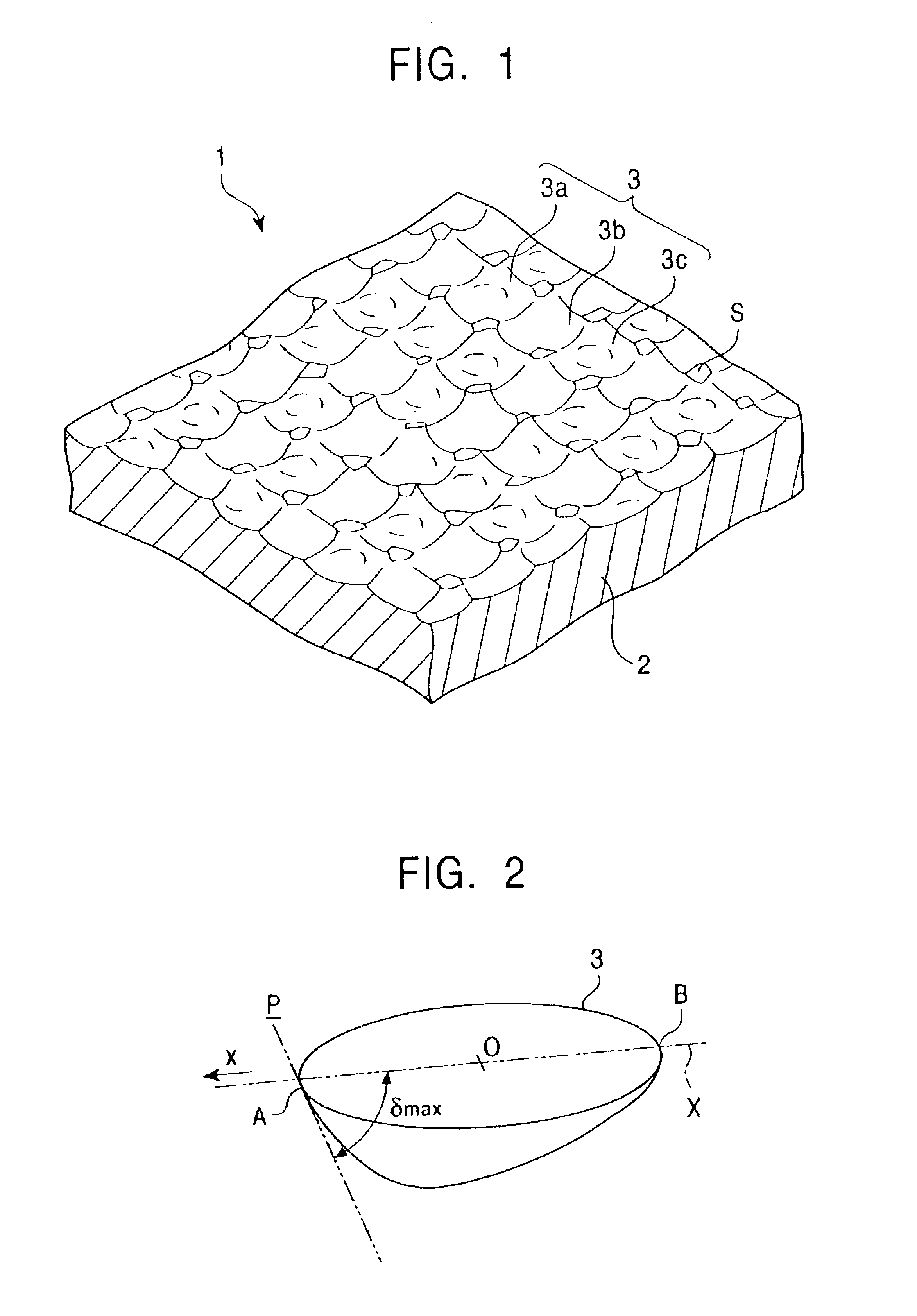
[0054]FIG. 1 is a diagram showing a reflector 1 according to an embodiment of the present invention. As shown in FIG. 1, the reflector 1 of the present embodiment is constructed of a plate-shaped substrate 2 formed of, for example, aluminum. A plurality of light-reflective concave portions 3a, 3b, 3c, . . . , (denoted as concave portions 3 when they are generically described) are irregularly formed next to each other on the surface S (standard surface) of the substrate 2.

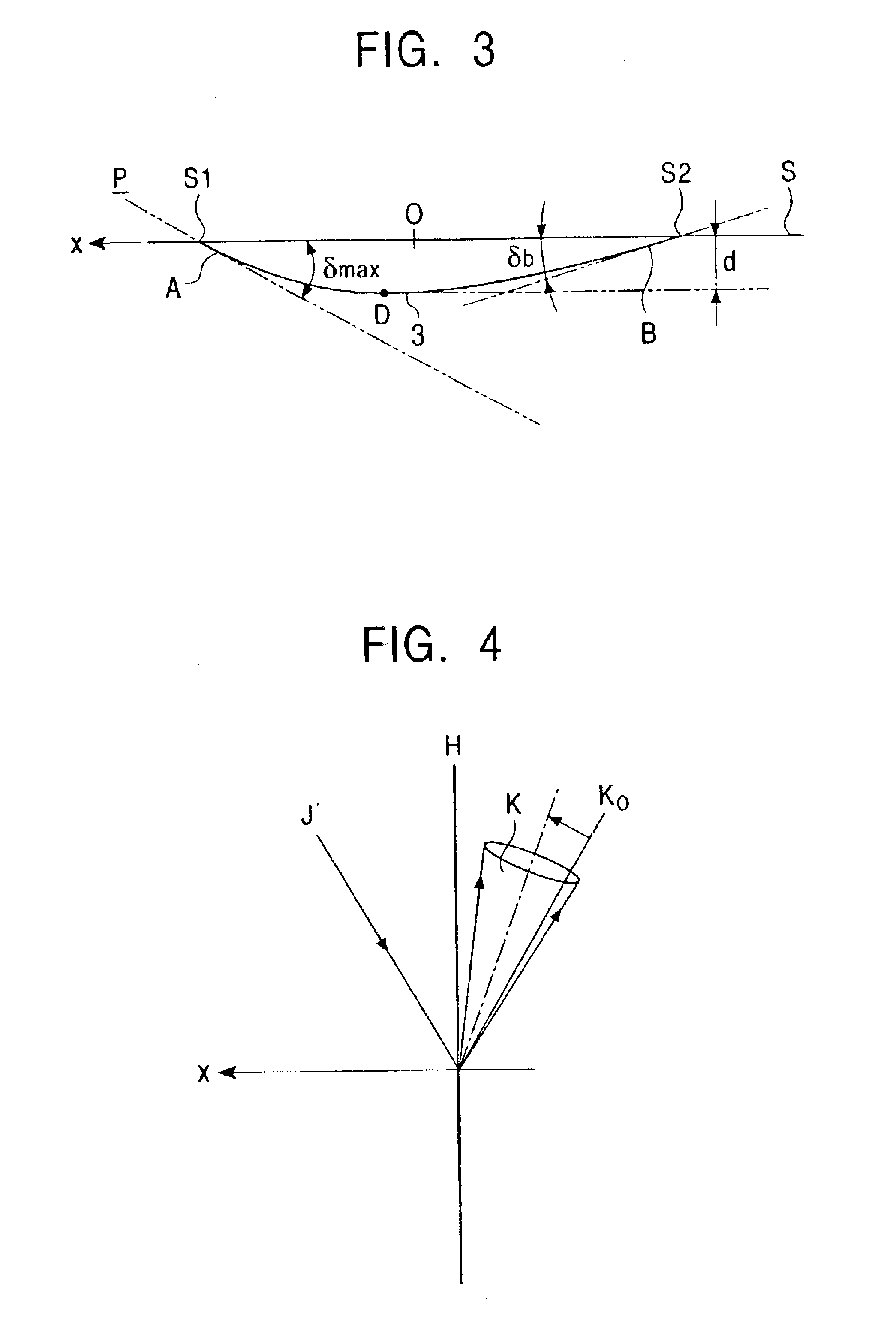
[0055]FIG. 2 and FIG. 3 are a perspective view and a sectional view, respectively, of the concave portion 3. As shown in FIGS. 2 and 3, the internal shape of the concave portion 3 along a specific vertical section X is defined by a first curve A and a second curve B, the first curve A extending from one point S1 on the peripheral edg...


PUM


Abstract

A reflector for a liquid crystal display includes a substrate with light-reflective concave portions on the surface thereof. Each concave portion has a specific vertical section which passes through a deepest point of the concave portion. The internal shape of the specific vertical section is defined by a first curve, which extends from one point on the peripheral edge of the concave portion to the deepest point of the concave portion, and a second curve, which extends continuously from the first curve and from the deepest point of the concave portion to another point on the peripheral edge of the concave portion. The average of the absolute value of an inclination angle of the first curve relative to the substrate surface is larger than the average of the absolute value of an inclination angle of the second curve relative to the substrate surface.

Description

[0001]This application claims the benefit of priority to Japanese Patent Application 2001-197360, filed on Jun. 28, 2001.BACKGROUND OF THE INVENTION[0002]1. Field of the Invention[0003]The present invention relates to reflectors and reflective liquid crystal displays, and more specifically relates to a reflector having reflection characteristics such that it appears brighter when reflection light is observed at a specific viewing angle than when it is observed at other viewing angles, and to a reflective liquid crystal display using the reflector.[0004]2. Description of the Related Art[0005]Liquid crystal displays can be generally classified into two types: transmissive liquid crystal displays and reflective liquid crystal displays. In reflective liquid crystal displays, external light is used for illumination and a front light is used for ensuring visibility. Reflective liquid crystal displays are commonly used as display units for electronic devices such as mobile computers, calcu...

Claims


Application Information

Patent Timeline
IPC IPC(8): G02F1/1335G02F1/13G02B5/08
CPCG02B5/08G02F1/133553G02F1/1335
Inventor YOSHII, KATSUMASAMORIIKE, TATSUYAOMOTE, KINJIKANO, MITSURU
Owner ALPS ALPINE CO LTD
Why Eureka
Try Eureka