

Reduced multicubic database interpolation method for optical measurement of diffractive microstructures
Inactive Publication Date: 2005-09-20
TOKYO ELECTRON LTD
View PDF9 Cites 63 Cited by
- Summary
- Abstract
- Description
- Claims
- Application Information
AI Technical Summary
Benefits of technology
[0023]As noted above, the interpolation method dramatically reduces the number of values that must be used during the interpolation step associated with computing the reflectance characteristics of a sample. For example, the number of values necessary to perform this interpolation when applied to a database wherein each point is defined by six parameters is only about one-tenth of the number of values needed with the multicubic approach. This computational savings increases for higher parameter problems (e.g.: with a seven p
Problems solved by technology
Evaluation of theoretical scatterometry models is a complex task, even for relatively simple subject.
As subjects become more complex, e.g., having more parameters, the calculations can become extremely time-consuming.
Even with high-speed processors, real-time evaluation of these calculations can be difficult.
This is problematic in semiconductor manufacturing where it is often imperative to detect processes that are not operating correctly.
Amdahl's law also limits the amount of speedup available by parallel processing since serial portions of the program are not improved.
At the present time, neither cost nor ultimate speed improvement is a serious limitation for parallel processing techniques.
As the complexity of the geometry increases, however it bec
Method used
View moreImage
Smart ImageViewing Examples

Examples
 PUM
 Abstract
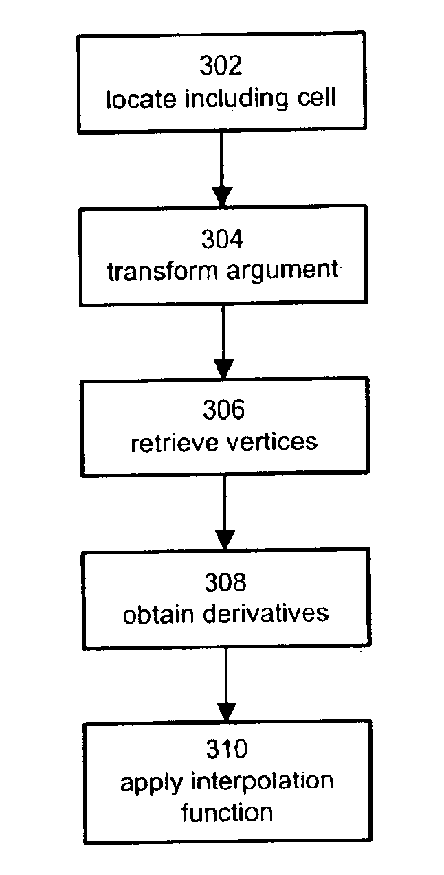
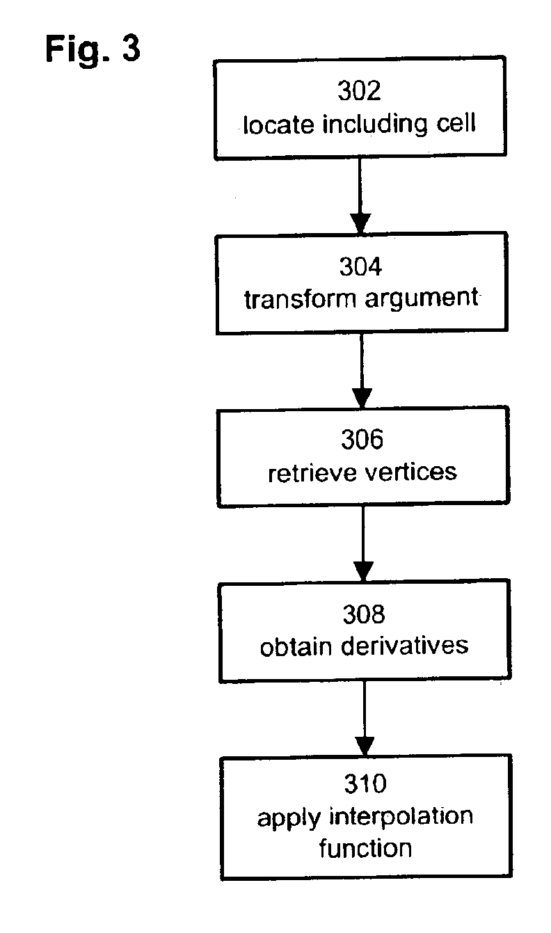
A reduced multicubic database interpolation method is provided. The interpolation method is designed to map a function and its associated argument into an interpolated value using a database of points. The database is searched to locate an interpolation cell that includes the function argument. The interpolation cell is used to transform the function argument to reflect translation of the interpolation cell to a unit cell. The interpolated value is then generated as a cubic function using the data points that correspond to vertices of the unit cell. All of the derivatives in the cubic function are simple and the interpolation accuracy order is higher than first-order.
Description
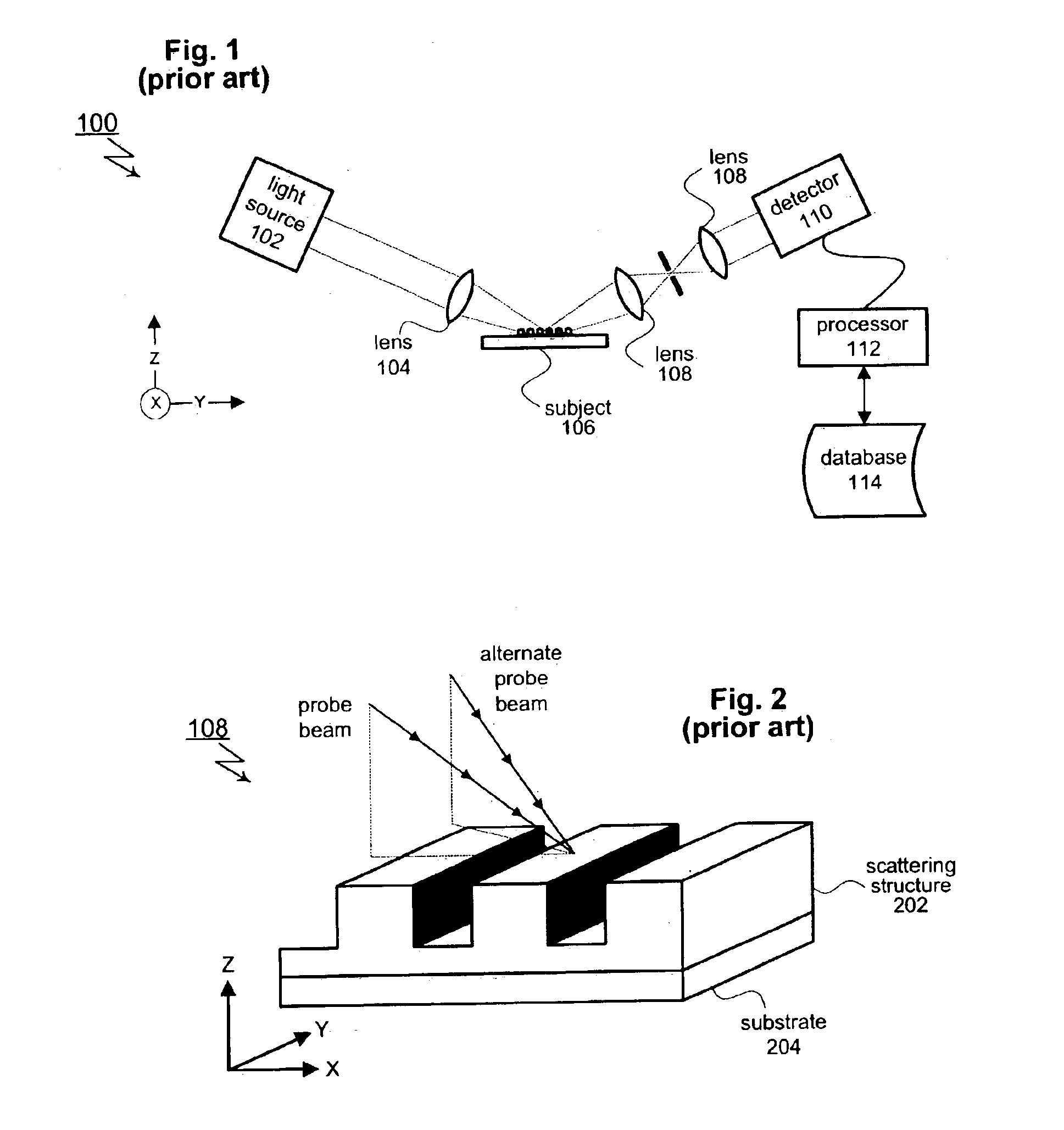
PRIORITY CLAIM[0001]The present application claims priority to U.S. Provisional Patent Application Ser. No. 60 / 392,953, filed Jul. 1, 2002 and U.S. Provisional Patent Application Ser. No. 60 / 426,602, filed Nov. 15, 2002. The disclosure of both of these documents is incorporated herein by reference.TECHNICAL FIELD[0002]The subject invention relates generally to optical methods for inspecting and analyzing semiconductor wafers and other samples. In particular, the subject invention relates to improvements in analysis of the measured optical signal characteristics from a sample to determine parameter values for that sample.BACKGROUND OF THE INVENTION[0003]As geometries continue to shrink, manufacturers have increasingly turned to optical techniques to perform non-destructive inspection and analysis of semiconductor wafers. Techniques of this type, known generally as optical metrology, operate by illuminating a sample with electromagnetic radiation and then detecting and analyzing the r...
Claims
Login to View More Application Information
Patent Timeline
 IPC IPC(8): G01N21/47G01N21/88G01N21/956G01N21/95
CPCG01N21/47G01N21/9501G01N21/956
InventorJOHNSON, KENNETH C.
OwnerTOKYO ELECTRON LTD