Information processing method, apparatus and storage medium for receiving and decoding a code sequence obtained by encoding an image

a technology of image data and information processing method, which is applied in the field of image processing method and apparatus for receiving and decoding image data, can solve the problems of distorted reproduced image beyond the allowable level due to quantization, image data size becomes huge, complicated apparatus, etc., and achieves high image quality

Inactive Publication Date: 2005-09-20
CANON KK
View PDF15 Cites 47 Cited by
  • Summary
  • Abstract
  • Description
  • Claims
  • Application Information

AI Technical Summary

Benefits of technology

[0009]The present invention has been made in consideration of the above prior arts, and has as its object to provide an image pro

Problems solved by technology

Among these data, an image, especially, a multi-valued image contains a very large volume of information, and upon storing and transmitting such image, the image data size becomes huge.
As a result, especially under a low-bit rate condition, the reproduced image is distorted beyond an allowable level due to quantization.
If hierarchical coding is implemented as reversible coding, since the spatial mode is us

Method used


Image

  • Information processing method, apparatus and storage medium for receiving and decoding a code sequence obtained by encoding an image
  • Information processing method, apparatus and storage medium for receiving and decoding a code sequence obtained by encoding an image
  • Information processing method, apparatus and storage medium for receiving and decoding a code sequence obtained by encoding an image

Examples


first embodiment

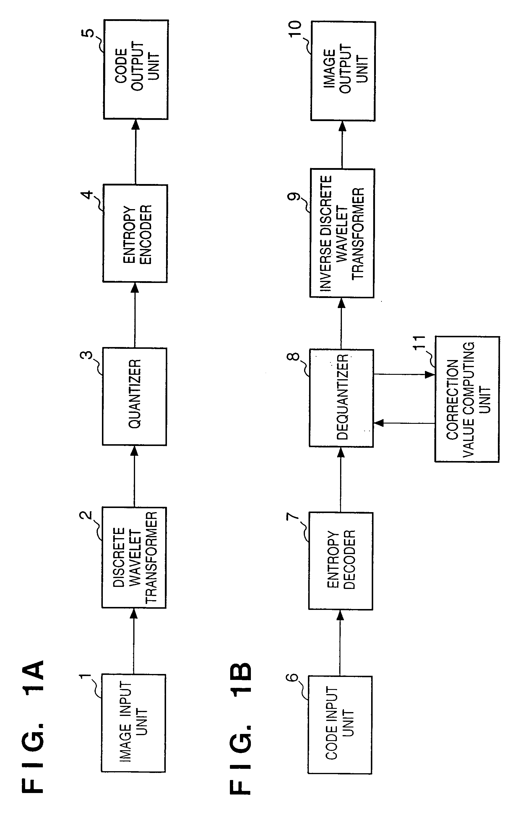
[0027]FIGS. 1A and 1B are block diagrams respectively showing the basic arrangements of image encoding and decoding apparatuses according to the first embodiment of the present invention.

[0028]FIG. 1A is a block diagram showing the arrangement of an image encoding apparatus. Referring to FIG. 1A, reference numeral 1 denotes an image input unit for inputting image data. The image input unit 1 comprises an image sensing device such as a scanner, digital camera, or the like for scanning a document image, an interface unit having an interface function, or the like. Reference numeral 2 denotes a discrete wavelet transformer for computing the two-dimensional discrete wavelet transform of the input image. Reference numeral 3 denotes a quantizer for quantizing coefficients obtained by discrete wavelet transformation. Reference numeral 4 denotes an entropy encoder for entropy-encoding the coefficients quantized by the quantizer 3. Reference numeral 5 denotes a code output unit for outputting...

second embodiment

[0071]In the first embodiment, after all the bit planes of a quantization index are decoded, dequantization is made to restore an image. Alternatively, the present invention can be applied to a case wherein an image is restored and displayed before decoding all the bit planes. The operation for restoring and displaying an image stepwise in a decoding apparatus according to the second embodiment of the present invention will be explained below.

[0072]An image display pattern upon restoring an image stepwise will be explained below with reference to FIGS. 9A and 9B.

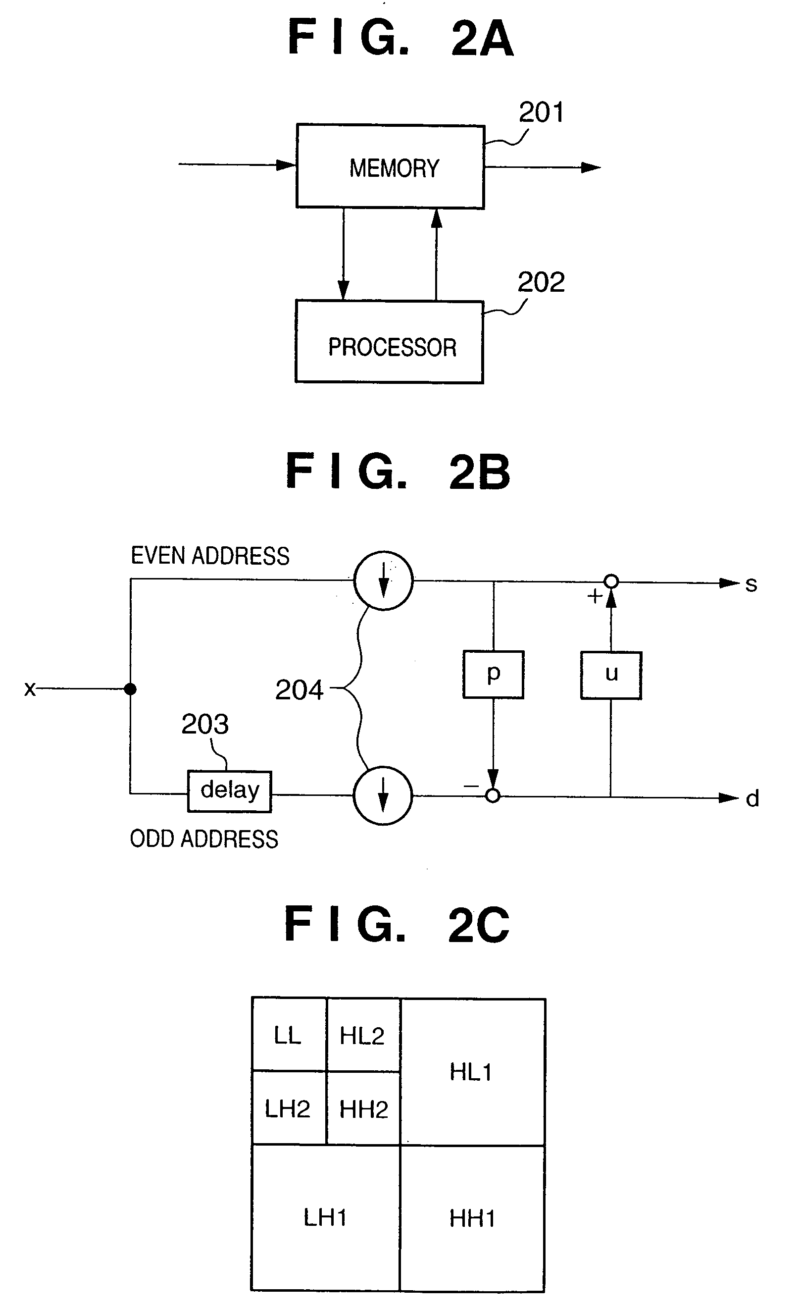
[0073]FIG. 9A shows an example of a code sequence, the basic format of which is based on FIGS. 4A to 4D, but the entire image is set as a tile in this case. Hence, the code sequence includes only one tile header (TH0) and bitstream (BS0). In this bitstream (BS0), codes are set from the most significant bit plane (Bit S-1) to the least significant bit plane (Bit 0).

[0074]The decoding apparatus according to the second embodime...

third embodiment

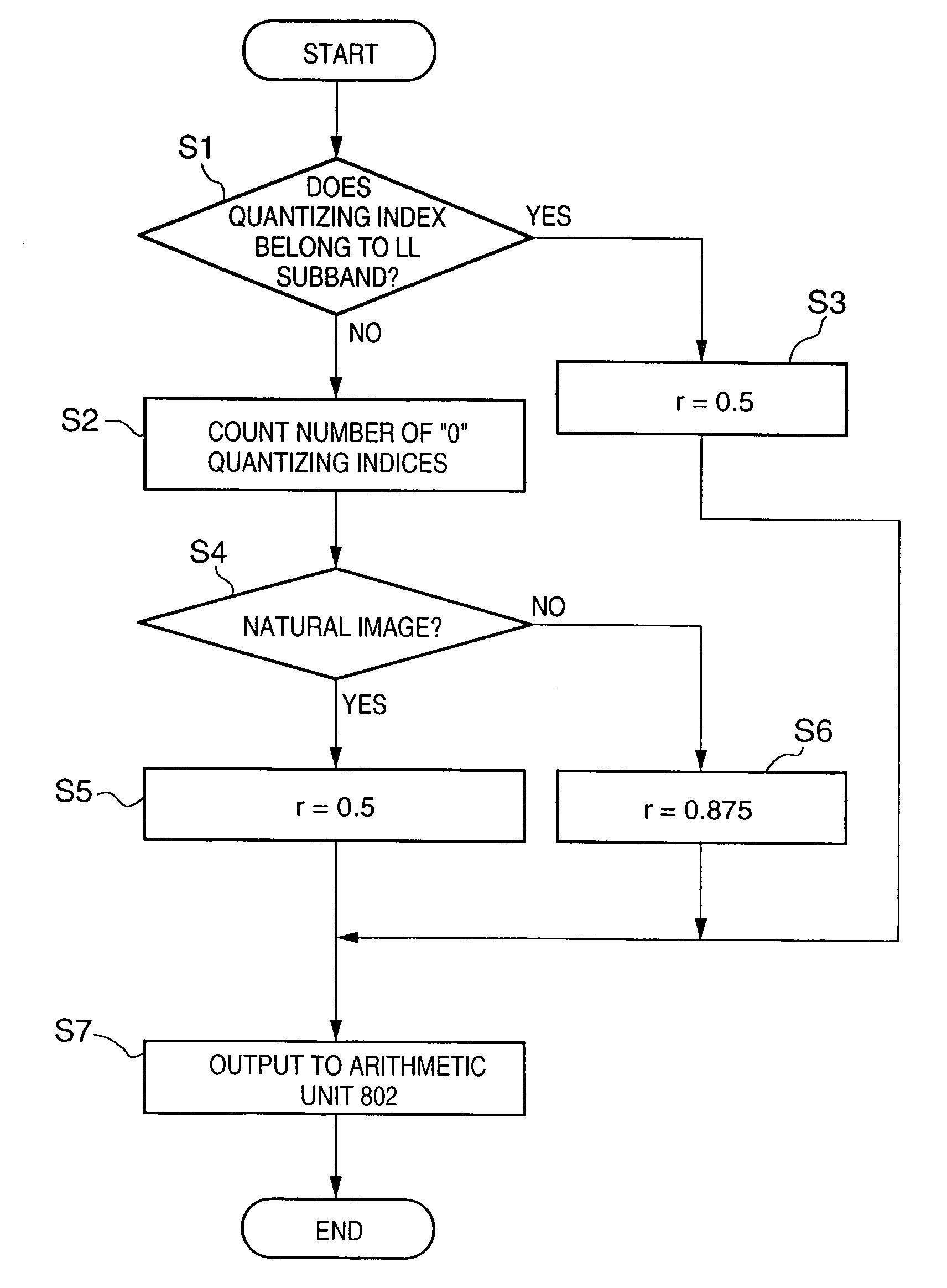
[0082]In the first and second embodiments described above, the correction value r is selected among a plurality of correction values, by referring to neighboring regions of the quantization index to be dequantized in dequantization. Alternatively, the image type may be discriminated at the time of encoding, and the correction value r may be selected upon decoding on the basis of the discrimination result. The third embodiment based on such scheme will be explained below.

[0083]FIGS. 11A and 11B are block diagrams showing the arrangements of image encoding and decoding apparatuses according to the third embodiment of the present invention.

[0084]FIG. 11A is a block diagram showing the arrangement of an encoding apparatus according to the third embodiment. The basic arrangement is substantially the same as that shown in FIG. 1A, except that the apparatus of the third embodiment comprises a region discriminator 12. That is, the image input unit 1 breaks up an input image into rectangular...


PUM


Abstract

An entropy decoder receives a code sequence which is obtained by breaking up coefficients that have undergone discrete wavelet transformation into bit planes, and encoding the bit planes, and entropy-decodes the code sequence. A correction value computing unit determines correction values used to correct dequantized values in a dequantizer in accordance with the number of quantization indices decoded by the entropy decoder. The dequantizer receives the quantization indices decoded by the entropy decoder, and generates a series of coefficient sequences that represent an image by correcting and dequantizing the quantization indices on the basis of the values of the quantization indices and the correction values obtained by the correction value computing unit. A predetermined inverse discrete wavelet transformer restores an image by computing the inverse transforms of the coefficient sequences obtained by the dequantizer, and outputs the restored image to an image output unit.

Description

FIELD OF THE INVENTION[0001]The present invention relates to an image processing method and apparatus for receiving and decoding a code sequence obtained by encoding image data, and a storage medium.BACKGROUND OF THE INVENTION[0002]Along with remarkable advances of computers and networks in recent years, many kinds of information such as text data, image data, audio data, and the like are stored or transmitted in the networks. Among these data, an image, especially, a multi-valued image contains a very large volume of information, and upon storing and transmitting such image, the image data size becomes huge. For this reason, storage and transmission of an image use high-efficiency coding that reduces the data size by removing redundancy of an image or changing the contents of an image to a degree at which deterioration of image quality is not visually recognizable.[0003]As an example of the high-efficiency coding, JPEG recommended by ISO and ITU-T as an international standard codin...

Claims


Application Information

Patent Timeline
IPC IPC(8): G06K9/36H04N7/30H04N1/41H04N19/60H04N19/124H04N19/134H04N19/136H04N19/157H04N19/33H04N19/34H04N19/44H04N19/46H04N19/63H04N19/70H04N19/91
CPCH04N19/647H04N19/63H04N19/129H04N19/44
Inventor SATO, MAKOTOKAJIWARA, HIROSHIKISHI, HIROKI
Owner CANON KK
Why Eureka
Try Eureka