Subscriber wireless access system

Inactive Publication Date: 2005-09-20
KOKUSA ELECTRIC CO LTD
View PDF16 Cites 17 Cited by
  • Summary
  • Abstract
  • Description
  • Claims
  • Application Information

AI Technical Summary

Benefits of technology

[0023]This makes it possible, for example, for an administration (operation) center that has received a subscriber request for the formation of a group to establish the desired group by remote operations with respect to the base stations.

Problems solved by technology

This is undesirable from a se

Method used


Image

  • Subscriber wireless access system
  • Subscriber wireless access system
  • Subscriber wireless access system

Examples


Embodiment Construction

[0030]The present invention will now be explained in detail with respect to the case where the communication protocol between the base station and the customer stations utilizes Ethernet frames tagged with VLAN-Tags conforming with IEEE 802.1Q.

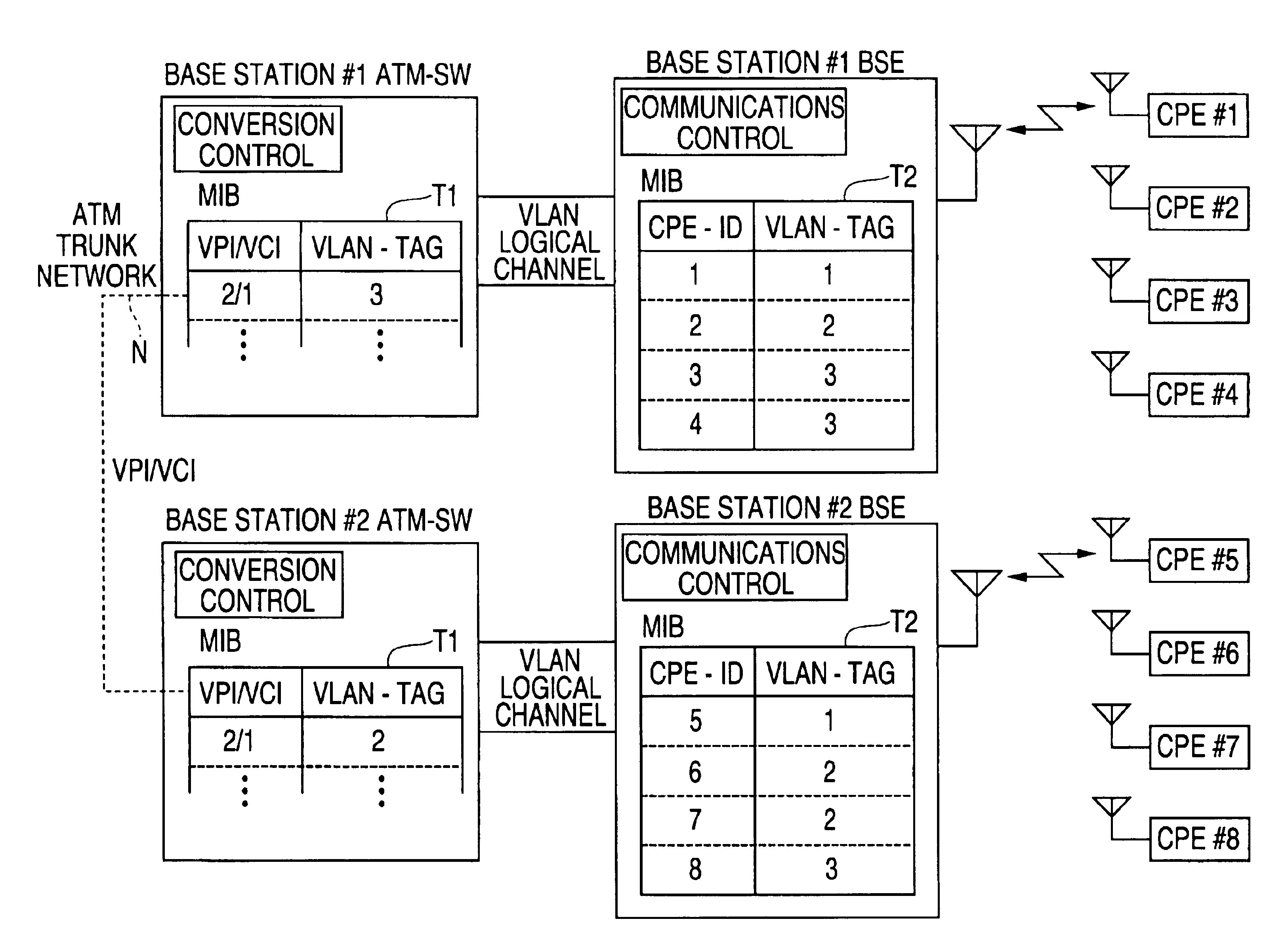
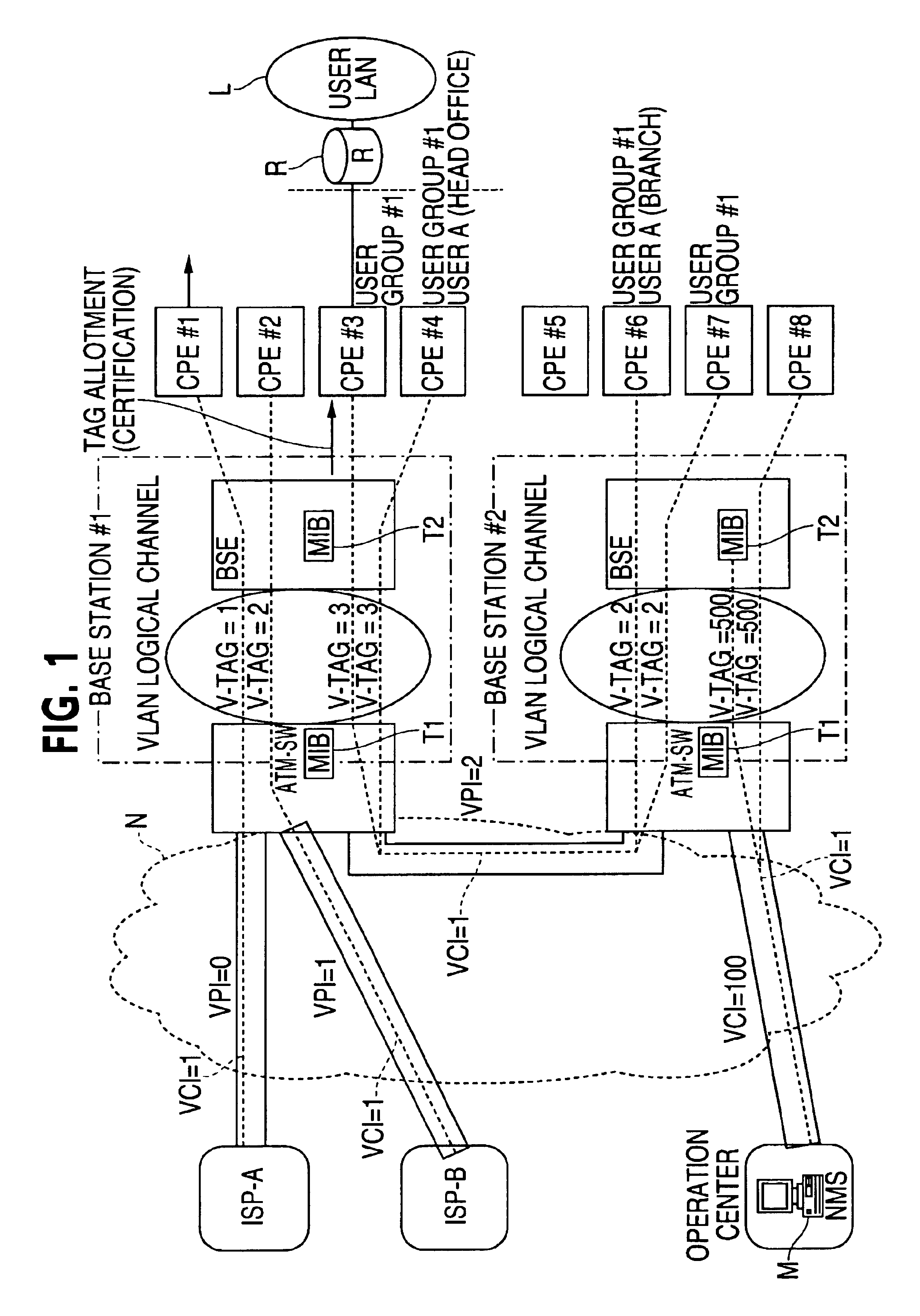
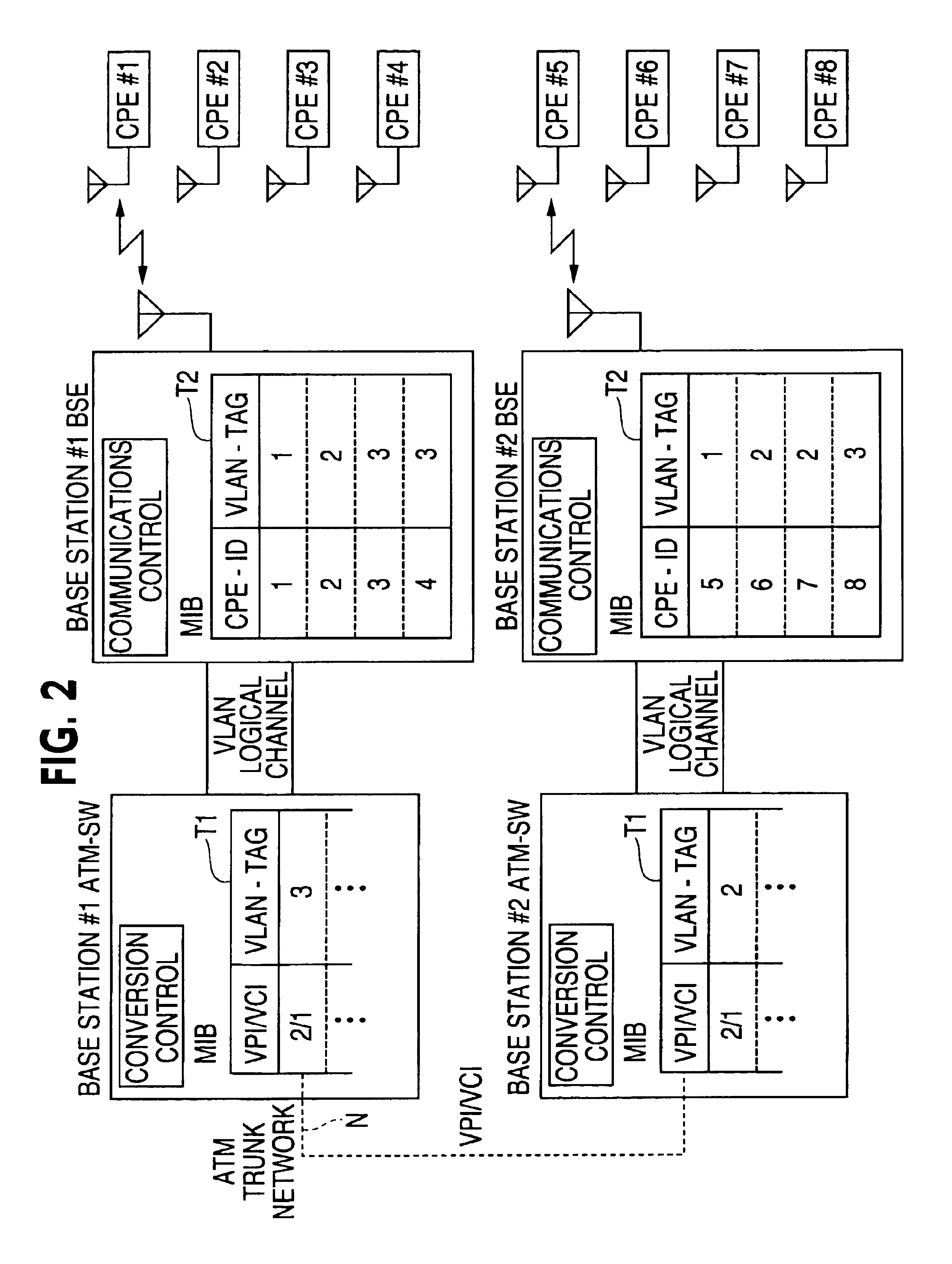
[0031]FIG. 1 is a block diagram of the subscriber wireless access system according to the present embodiment. FIG. 2 is a diagram showing the contents of correlation tables of the exchanges and base stations.

[0032]As shown in FIG. 1, multiple base stations are connected by SNMP via an ATM trunk network N, which is a virtual dedicated line network. Each base station accommodates a number of customer stations which are wirelessly connected by Ethernet frames. Each customer station is connected through a router R with a local area network L accommodating a large number of communication terminal devices (PCs; not shown).

[0033]The ATM trunk network N is connected with various servers of Internet service providers (ISP-A, ISP-B) and the like. The AT...


PUM


Abstract

A subscriber wireless access system equipped with customer stations wirelessly connected to base stations and accommodating communication terminal devices in the customer stations. The system is provided with at least one exchange for connecting the base stations with a virtual dedicated line network for enabling customer stations wirelessly connected to different base stations to be interconnected via a virtual dedicated line network. The exchange includes table information assigned to the customer stations with virtual network connection information allocated for connected the customer stations, means responsive to receipt of data from a customer station via a subordinate base station for, with reference to the table, sending the data through the virtual network to another base station, and means responsive to receipt of data through the virtual network for, with reference to the table, converting the data to customer station identification information and sending the data to a subordinate base station.

Description

FIELD OF THE INVENTION[0001]The present invention relates to a subscriber wireless access system for accommodating, in a customer station which is wirelessly connected to a base station, personal computers and other such communications terminal devices, or a LAN connected to such communication terminal devices. (A subscriber wireless access system of this type is also called, for example, a fixed wireless access (FWA) system.) More particularly, the present invention relates to a technology for controlling communications through a virtual dedicated line network which is implemented by an ATM (asynchronous transfer mode) network or the like.DESCRIPTION OF THE PRIOR ART[0002]Personal computers, mobile tools, mobile telephones and various other kinds of communication terminal equipment have recently become common items of everyday use. Wireless LANs for wirelessly interconnecting such communications terminal devices have been developed and put into operation.[0003]Subscriber wireless a...

Claims


Application Information

Patent Timeline
IPC IPC(8): H04L12/28H04L12/46H04W76/02H04L12/70H04W4/18H04W8/26H04W40/32H04W84/12H04W84/14H04W84/16H04W92/20
CPCH04L12/4645H04W4/18H04W8/26H04W92/20
Inventor YOKOYAMA, NAOKI
Owner KOKUSA ELECTRIC CO LTD
Why Eureka
Try Eureka