Method for geolocating logical network addresses

a network address and logical network technology, applied in the field of networked communication, can solve the problems of data propagation through non-constant routing, data to effectively propagate at a non-constant speed, and the geolocation tenets that support these geolocation methodologies are not applicable to the network environment, so as to achieve the effect of increasing the density of endpoints and enhancing the potential geolocation resolution

Inactive Publication Date: 2005-09-20
GOVERNMENT OF THE UNITED STATES AS REPRESENTED BY THE DIRECTOR NAT SECURITY AGENCY
View PDF6 Cites 118 Cited by
  • Summary
  • Abstract
  • Description
  • Claims
  • Application Information

AI Technical Summary

Benefits of technology

[0015]Another object of the present invention is to provide a method for determining the physical location of network hardware using a logical network address on a non-linear electronically switched dynamic network without reliance on time-distance correlations.
[0017]This invention describes a methodology for geolocation in a non-linear electronically switched dynamic network environment. The instant invention uses the latency of communications to and from an address to be located (ATBL) to determine its location. In order to do this a network latency topology map must first be created. The network latency topology is mapped by measuring the round-trip latency between one or more network stations of known location and many network endpoints, which can themselves be network stations, of known location. Endpoints are chosen to be points dispersed across the network within the area where geolocations will be performed. Potential geolocation resolution is enhanced with an increasing density of endpoints.

Problems solved by technology

In addition to the direction of the signal, other linear characteristics can be used to geolocate signals, including propagation time and Doppler shift, but the underlining tenets that support these geolocation methodologies are not applicable to a network environment.
Network elements are not connected via the shortest physical path between them, data transiting the network is normally queued and later forwarded depending on network loading causing the data to effectively propagate at a non-constant speed, and switching elements within the network can cause the data to propagate through non-constant routing.
Thus, traditional time-distance geolocation methodologies are not effective in a network environment.
Network switching and queuing delays produced echo distance results several orders of magnitude greater than the actual distance between the computers.
Third, if the supplied physical address given cannot be cross-referenced to a physical location no geolocation is possible.
Geolocation information is often available from network databases but access to and the veracity of this information is uncertain.

Method used


Image

  • Method for geolocating logical network addresses
  • Method for geolocating logical network addresses
  • Method for geolocating logical network addresses

Examples


Embodiment Construction

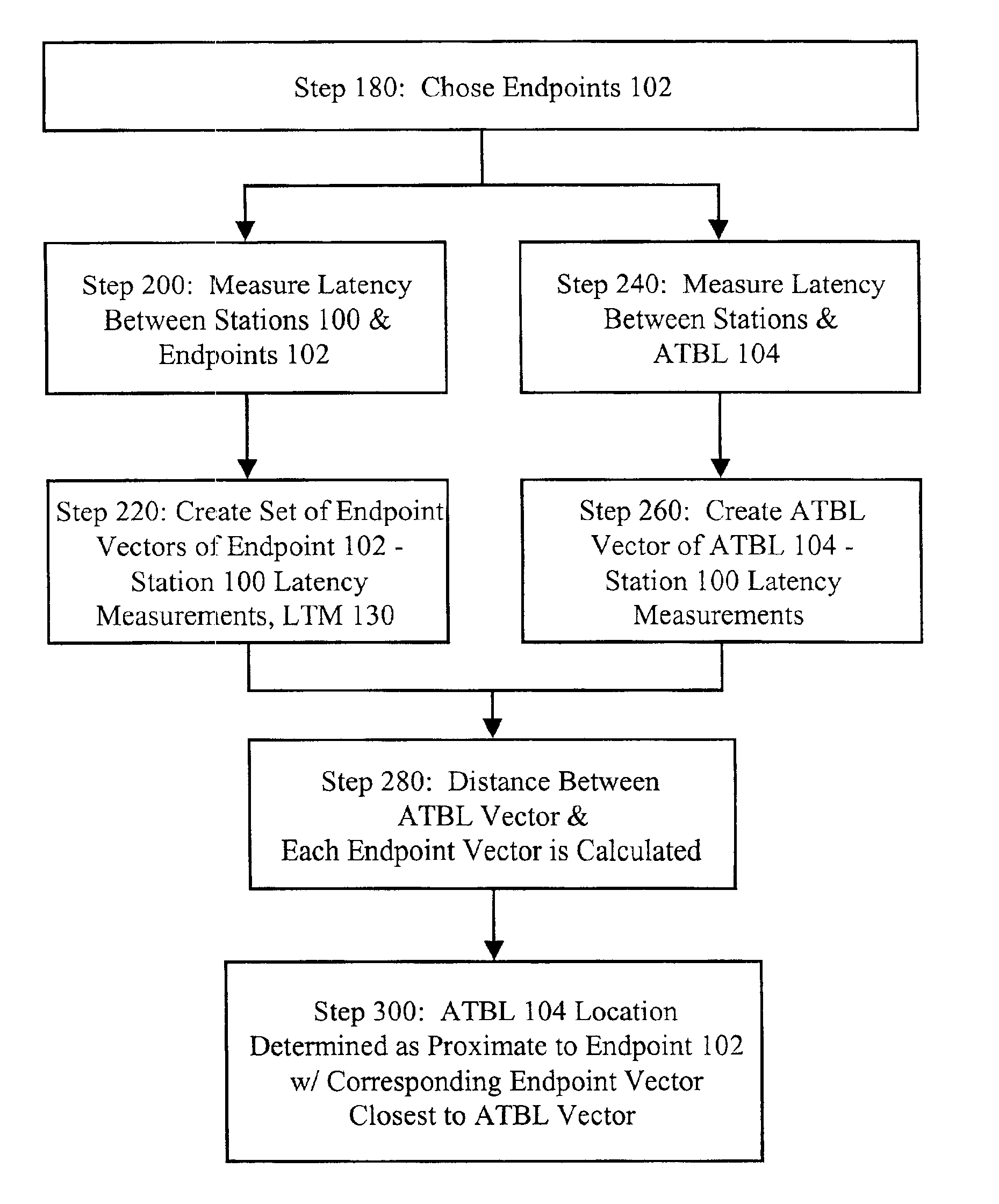
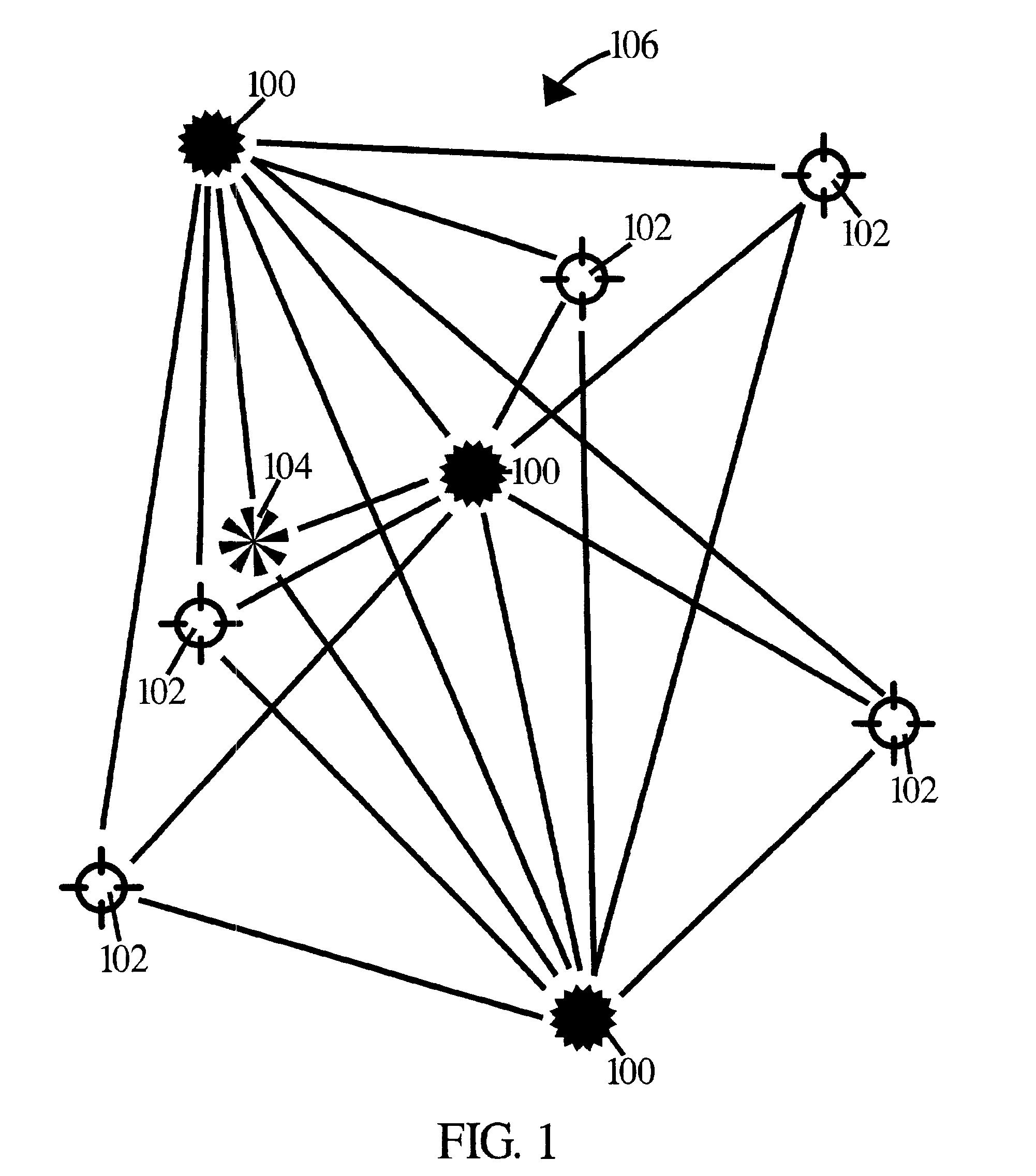
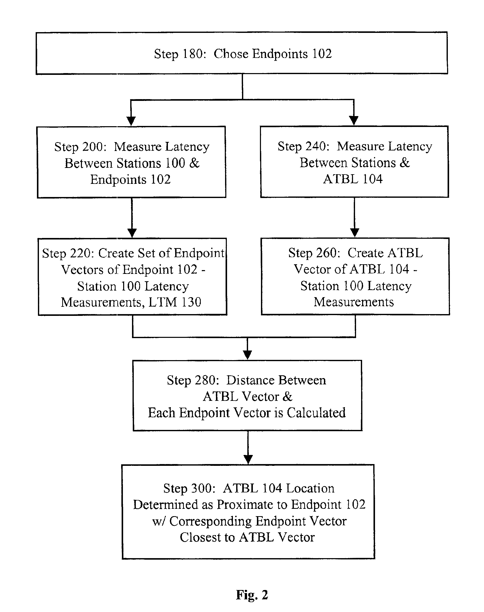
[0024]In order to geolocate an address to be located (ATBL) 104 on a non-linear electronically switched network 106 as depicted in FIG. 1 the signaling propagation characteristics of the network 106 must be measured. Signaling propagation across a network is measured as a latency. In the instant methodology this latency will be measured as the time it takes for a message to go from a station 100 to some specific addressed equipment, producing an immediate automated response, and back to the originating station 100. That specific addressed equipment can be either an endpoint 102, an ATBL 104, or another station 100. The aggregate of this round-trip latency characteristic for many stations 100, each measuring latency to many endpoints 102, is a latency topology map 130 (See FIG. 3) which characterizes the network latency among network stations 100 and endpoints 102.

[0025]Data moves through a network 106 at different rates depending on the amount of traffic being handled, the physical ...


PUM


Abstract

Method for geolocating logical network addresses on electronically switched dynamic communications networks, such as the Internet, using the time latency of communications to and from the logical network address to determine its location. Minimum round-trip communications latency is measured between numerous stations on the network and known network addressed equipment to form a network latency topology map. Minimum round-trip communications latency is also measured between the stations and the logical network address to be geolocated. The resulting set of minimum round-trip communications latencies is then correlated with the network latency topology map to determine the location of the network address to be geolocated.

Description

FIELD OF THE INVENTION[0001]The present invention, a Method for Geolocating Logical Network Addresses, relates to networked communications, and more particularly to a method for determining or verifying the physical location of a logical network address.BACKGROUND OF THE INVENTION[0002]As more of the nation's commerce and communication have moved from traditional fixed-point services to electronically switched networks the correlation between who you are communicating or doing business with and where they are physically located no longer exists. In the past, communication and commerce took place between parties at known physical locations, whether across a store counter or between post office addressees. Even telephone numbers correlated, more or less, to a permanent fixed location.[0003]There are still many advantages to knowing the physical location of a party one is dealing with across electronically switched networks. For example, in the realm of advertising, knowing the geograp...

Claims


Application Information

Patent Timeline
Patent Type & Authority Patents(United States)
IPC IPC(8): H04L29/12H04L12/24
CPCH04L29/12009H04L29/12207H04L41/12H04L43/0852H04L61/20H04L61/50H04L61/00
Inventor HUFFMAN, STEPHEN MARKREIFER, MICHAEL HENRY
Owner GOVERNMENT OF THE UNITED STATES AS REPRESENTED BY THE DIRECTOR NAT SECURITY AGENCY
Why Eureka
Try Eureka