
Rankine cycle system

Inactive Publication Date: 2005-09-27
HONDA MOTOR CO LTD
View PDF15 Cites 15 Cited by
  • Summary
  • Abstract
  • Description
  • Claims
  • Application Information

AI Technical Summary

Benefits of technology

[0009]In accordance with this arrangement, since the working medium separating means that exhibits the function of separating the working medium in the predetermined temperature range is provided at a position where the temperature of the lubricating medium is in the predetermined temperature range, the function of separating the working medium can be exhibited stably while preventing any damage to the working medium separating means.
[0031]In accordance with this arrangement, when separating the working medium contained in the lubricating medium of the expander by the working medium separating means, since the lubricating medium is a hydrophobic oil containing no extreme pressure additive having surface activity, it is possible to prevent any degradation in the lubrication performance due to emulsification of the lubricating medium and, moreover, the ability to separate the working medium and the lubricating medium can be improved.

Problems solved by technology

When a lubricating medium of an expander has become mixed with a working medium circulating around a closed circuit of a Rankine cycle system, the amount of lubricating medium in the expander becomes insufficient, thus degrading the efficiency of the expander or causing seizing.
However, in the Rankine cycle system disclosed in Japanese Utility Model Publication No. 61-8170, since the mixture of the working medium and the lubricating medium circulates in the closed circuit, there is a possibility that the lubricating medium in the working medium circulating in the closed circuit might gasify due to heat, thus affecting the performance and the durability of the Rankine cycle system.
Furthermore, since a mixture of liquid-phase working medium, gas-phase working medium, and lubricating medium is supplied from a boiler to the gas / liquid separator and, moreover, the gas / liquid separator has a structure in which the lubricating medium is separated by gravity, there is the problem that it is impossible to prevent the liquid-phase working medium from becoming mixed with the lubricating medium.

Method used


Image

  • Rankine cycle system
  • Rankine cycle system
  • Rankine cycle system

Examples


Embodiment Construction

[0058]An embodiment of the present invention is explained below with reference to the attached drawings.

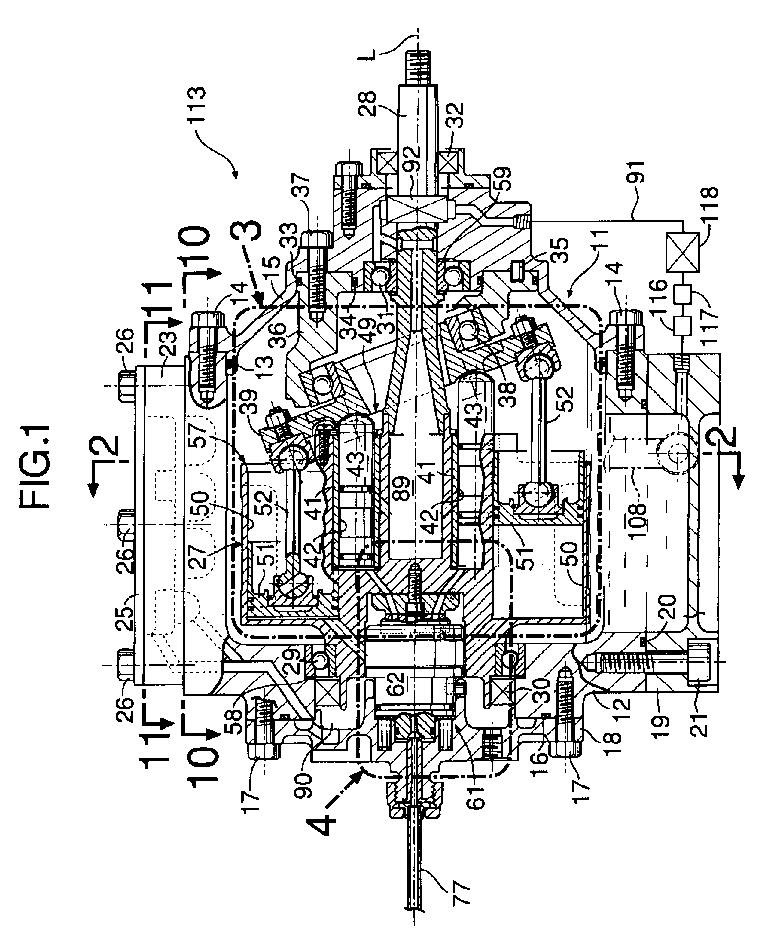
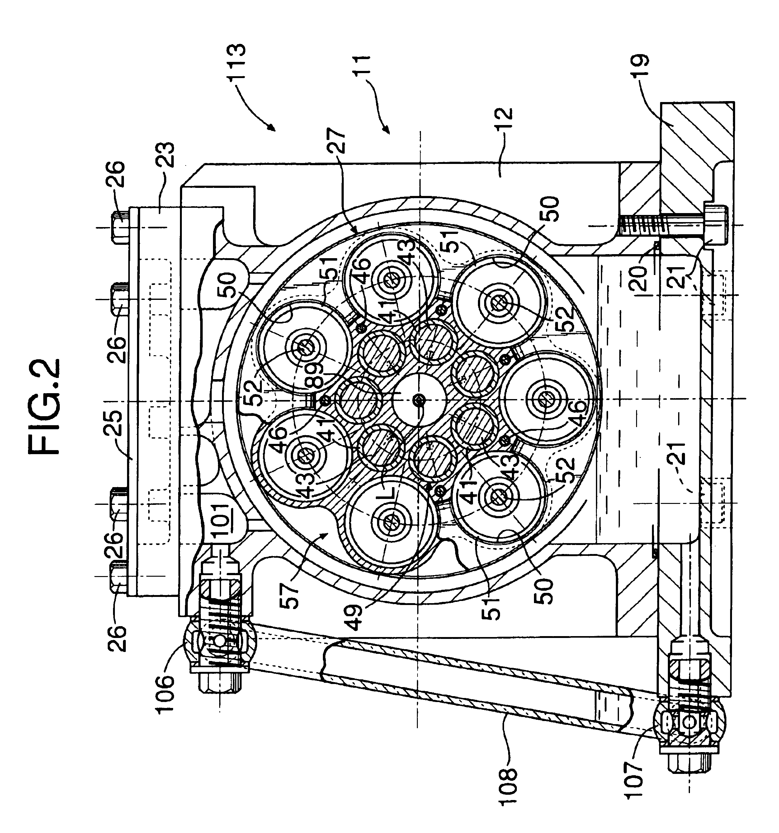
[0059]Firstly, an outline of the structure of an expander 113 of a Rankine cycle system is explained with reference to FIG. 1 to FIG. 3.

[0060]The expander 113 converts the thermal energy and the pressure energy of high-temperature, high-pressure steam as a working medium into mechanical energy and outputs it. A casing 11 of the expander 113 is formed from a casing main body 12, a front cover 15 fitted via a seal 13 into a front opening of the casing main body 12 and joined thereto via a plurality of bolts 14, and a rear cover 18 fitted via a seal 16 onto a rear opening of the casing main body 12 and joined thereto via a plurality of bolts 17. An oil pan 19 abuts against a lower opening of the casing main body 12 via a seal 20 and is joined thereto via a plurality of bolts 21. Furthermore, a breather chamber dividing wall 23 is superimposed on an upper surface of the casing main bo...


PUM


Abstract

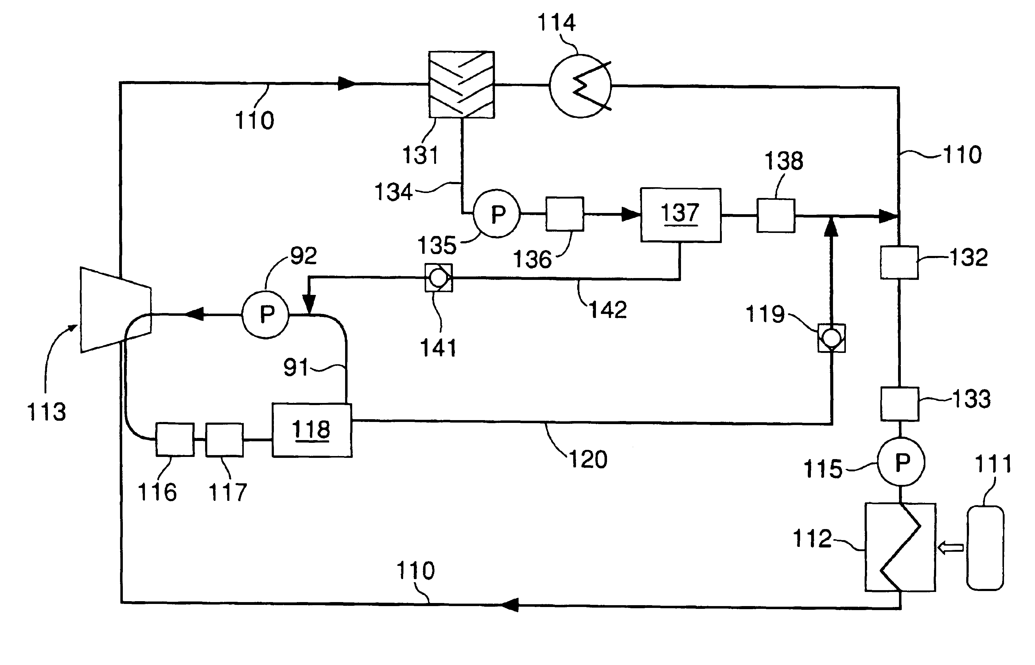
A Rankine cycle system having a working medium circulation circuit (110) that includes an evaporator (112), an expander (113), a condenser (114), and a feed pump (115) is provided in which a mixture of oil for lubricating the expander (113) and water, which is a working medium and has become mixed with the oil, is supplied to coalescer type water separating means (118), thus separating the water from the oil. The oil from which water has been separated in water separating means (118) is returned to the expander (113), and the water separated from the oil is returned to the working medium circulation circuit (110). It is thus unnecessary to replenish the working medium circulation circuit (110) with water or replenish the expander (113) with oil.

Description

FIELD OF THE INVENTION[0001]The present invention relates to a Rankine cycle system having an evaporator, an expander, a condenser, and a feed pump provided along a working medium circulation circuit and, in particular, to a Rankine cycle system provided with means for separating a working medium that has become mixed with a lubricating medium of the expander, or to a Rankine cycle system provided with means for separating the lubricating medium of the expander that has become mixed with the working medium.BACKGROUND ART[0002]When a lubricating medium of an expander has become mixed with a working medium circulating around a closed circuit of a Rankine cycle system, the amount of lubricating medium in the expander becomes insufficient, thus degrading the efficiency of the expander or causing seizing. Japanese Utility Model Publication No. 61-8170 discloses a gas / liquid separator for separating a lubricating medium from a working medium and returning it to an expander.[0003]There is ...

Claims


Application Information

Patent Timeline
IPC IPC(8): F01B17/04F01B17/00F01B3/00F01B3/02F01B21/02F01B21/00F01K7/00F01K25/00F01K25/08F01D25/18B01D17/00B01D17/022F03C1/253F25B43/02
CPCF01B3/02F01B17/04F01B21/02F01K7/00F01K25/08
Inventor MINEMI, MASAHIKOTANIGUCHI, HIROYOSHI
Owner HONDA MOTOR CO LTD
Learn More