Hermetic reciprocating compressor

a reciprocating compressor and hermetic technology, which is applied in the direction of positive displacement liquid engines, piston pumps, lighting and heating apparatus, etc., can solve the problems of severe friction between the rotating shaft and the shaft bore of the frame, the friction between the rotating shaft and the shaft bore may undetectedly move in the shaft bore, etc., to reduce the noise of the compressor, improve the compression efficiency of the compressor, and minimize frictional contact

Inactive Publication Date: 2005-09-27
SAMSUNG GWANGJU ELECTRONICS CO LTD
View PDF7 Cites 23 Cited by
  • Summary
  • Abstract
  • Description
  • Claims
  • Application Information

AI Technical Summary

Benefits of technology

[0015]Accordingly, it is an aspect of the present invention to provide a hermetic reciprocating compressor, in which a bearing structure to support a rotating shaft is improved to minimize frictional contact between parts of the compressor, thus reducing noise of the compressor and improving compression efficiency of the compressor.

Problems solved by technology

However, the conventional hermetic reciprocating compressors are problematic as follows.
Since the rotating shaft is held with friction within the shaft bore as described above, the rotating shaft may undesirably move in the shaft bore.
In such a case, severe friction occurs at the junction between the rotating shaft and the shaft bore of the frame.
The conventional hermetic reciprocating compressors thus easily generate noise to upset those around the compressors.
The frictional contact of the rotating shaft with the shaft bore of the frame also undesirably reduces compression efficiency of the compressors.
However, the machining of the spiral oil groove around the rotating shaft complicates a production process of the compressors.
Furthermore, it is difficult to machine the spiral oil groove around the outer surface of the rotating shaft.
However, the conventional hermetic reciprocating compressors may not always form the desired perpendicular arrangement of the shaft bore relative to the cylinder block, due to a mechanical tolerance of the frame.
In such a case, severe friction occurs at the junction between the rotating shaft and the shaft bore to cause excessive wear on the rotating shaft and the shaft bore, in addition to generating noise.

Method used


Image

  • Hermetic reciprocating compressor
  • Hermetic reciprocating compressor
  • Hermetic reciprocating compressor

Examples


first embodiment

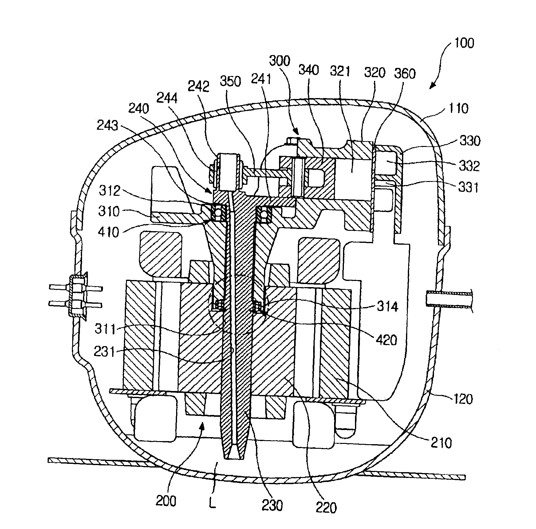
[0031]FIG. 1 is a side sectional view showing the construction of a hermetic reciprocating compressor, according to the present invention.

[0032]As shown in FIG. 1, the hermetic reciprocating compressor according to the first embodiment of the present invention has a hermetic casing 100 which is fabricated with upper and lower casing parts 110 and 120 assembled into a hermetic single body. A compression unit 300 to compress an inlet gas refrigerant, and a drive unit 200 to generate a drive power for the compression unit 300 are installed in the hermetic casing 100.

[0033]In the hermetic reciprocating compressor, the compression unit 300 has a cylinder block 320, which is integrally formed in a frame 310 to define a compression chamber 321 therein. A cylinder head 330 is mounted to the cylinder block 320. The cylinder head 330 has both a suction chamber 331 to guide the gas refrigerant into the compression chamber 321, and an exhaust chamber 332 to guide the compressed refrigerant from...

second embodiment

[0058]As shown in FIGS. 5 and 6, the hermetic reciprocating compressor according to the present invention includes a second radial bearing 420, in addition to the first radial bearing 410. The second radial bearing 420 is seated in a second annular bearing seat 314 which is formed around a lower edge of the shaft bore 311. The second radial bearing 420 has a second outer race 421 and a second inner race 422 which are concentric rings, with a plurality of second balls set in a ball seat space defined between the outer and inner races 421 and 422. The second outer race 421 is securely fitted in the second bearing seat 314 of the frame 310, while the second inner race 422 is set around the rotating shaft 230 with friction.

[0059]The rotating shaft 230 has a stepped part at a predetermined section of an outer surface thereof so as to secure a gap between the outer surface of the rotating shaft 230 and the inner surface of the shaft bore 311. The stepped part of the rotating shaft 230 ext...

third embodiment

[0067]In the hermetic reciprocating compressor according to the present invention, the eccentric shaft 242 of the eccentric part 240 of the rotating shaft 230 is connected to the piston 340 through the connecting rod 350, so that the eccentric rotation of the eccentric shaft 242 is converted into the rectilinear reciprocation of the piston 340 within the compression chamber 321. In such a case, the connecting rod 350 has a shaft guide 351 at a first end thereof to be rotatably connected at the shaft guide 351 to the eccentric shaft 242, and is connected to the piston 340 at a second end thereof.

[0068]The hermetic reciprocating compressor according to the third embodiment has a third radial bearing 430, in addition to the first radial bearing 410. The third radial bearing 430 is set in a junction between the outer surface of the eccentric shaft 242 and the shaft guide 351 of the connecting rod 350. The third radial bearing 430 has a third outer race 431 and a third inner race 432 whi...


PUM


Abstract

A hermetic reciprocating compressor, in which a bearing structure to support a rotating shaft is improved to minimize frictional contact between the parts of the compressor, thus reducing noise of the compressor and improving compression efficiency of the compressor. In the hermetic reciprocating compressor, a first annular bearing seat is formed around an upper edge of a shaft bore of a frame to seat therein a first radial bearing which sustains loads of a rotating shaft. The first radial bearing is a self-aligning radial bearing which allows the rotating shaft to self-align due to a clearance angle of the first radial bearing, even when a desired perpendicular arrangement of the shaft bore relative to a cylinder block is not formed, due to a mechanical tolerance of the frame. The first radial bearing sustains both axial loads of the rotating shaft and horizontal loads acting in the rotating shaft due to rectilinear reciprocation of a piston, thus reducing the losses caused by friction between the rotating shaft and the frame. In addition, since the rotating shaft self-aligns due to the first radial bearing, it is possible to reduce the losses caused by friction between a compression chamber and the piston and between the rotating shaft and the frame.

Description

CROSS-REFERENCE TO RELATED APPLICATION[0001]This application claims the benefit of Korean Application No. 2003-29489, filed May 9, 2003, in the Korean Intellectual Property Office, the disclosure of which is incorporated herein by reference.BACKGROUND OF THE INVENTION[0002]1. Field of the Invention[0003]The present invention relates, in general, to hermetic compressors and, more particularly, to a hermetic reciprocating compressor which uses a radial bearing capable of smoothly operating the parts of the compressor.[0004]2. Description of the Related Art[0005]Generally, compressors are machines that compress a substance, such as a gas refrigerant, to reduce a volume of the substance or change a phase of the substance. As an example of the compressors, hermetic reciprocating compressors, which are housed in hermetic casings and in which a rotation of a shaft is converted into a rectilinear reciprocation of a piston within a compression chamber, are typically used in refrigeration sys...

Claims


Application Information

Patent Timeline
IPC IPC(8): F01B9/00F04B39/00F04B35/00F04B39/02F04B35/04F16C25/00F16C9/00F16C9/03F16C25/08F25B1/02
CPCF04B39/0094F04B39/0253F04B39/00
Inventor KIM, JIN UG
Owner SAMSUNG GWANGJU ELECTRONICS CO LTD
Why Eureka
Try Eureka