Shift device for vehicle
a technology for shifting devices and vehicles, applied in mechanical devices, transportation and packaging, propulsion unit arrangements, etc., can solve the problems of limited installation position of the shift device, limited space for and only manipulating the shift lever
- Summary
- Abstract
- Description
- Claims
- Application Information
AI Technical Summary
Problems solved by technology
Method used
Image
Examples
first embodiment
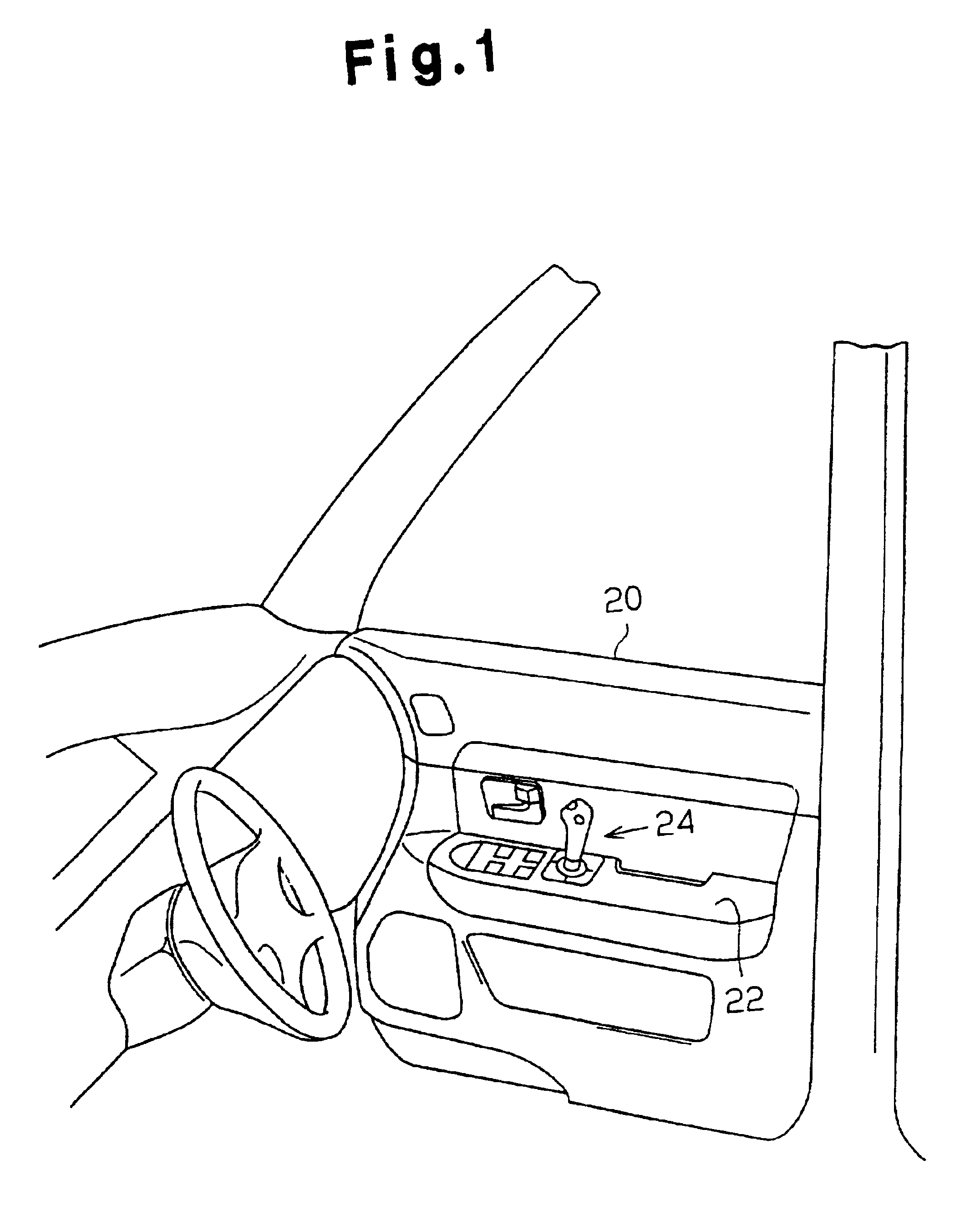
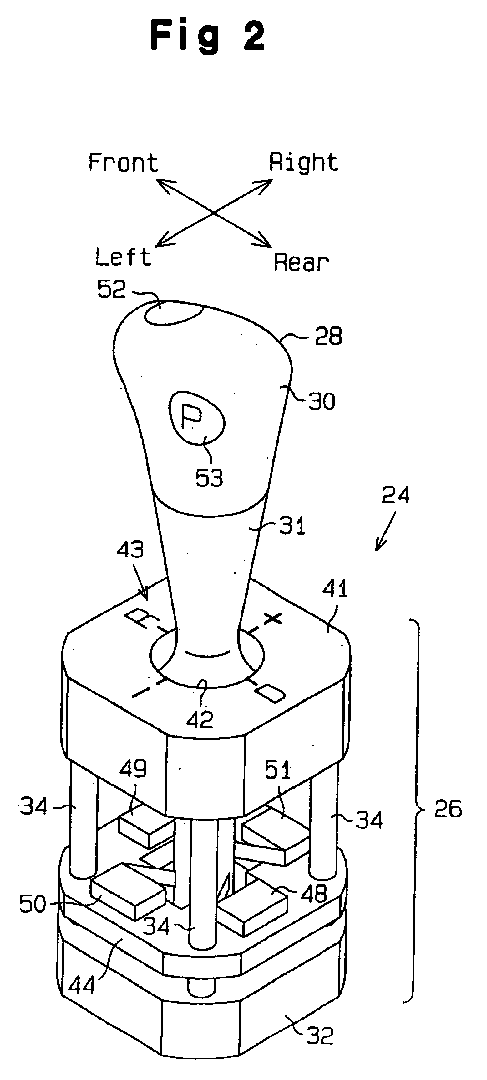
[0029]A first embodiment of the present invention will now be described with reference to FIGS. 1 to 6.
[0030]FIG. 5 is a schematic diagram illustrating a vehicle that is provided with an automatic transmission and its controller according to the first embodiment.
[0031]As shown in FIG. 5, an output shaft (not shown) of an engine 2 is connected to a torque converter 4. The torque converter 4 adjusts and transmits the rotational torque of the output shaft of the engine 2 to an automatic transmission (hereinafter, referred to as A / T) 6 through a fluid.
[0032]A hydraulic controller 8 within the A / T6 includes an electric actuator, which is a motor 10 in the first embodiment, for shifting gear ranges. The motor 10 is controlled by an electronic control unit (ECU) for automatic transmission (A / T ECU) 58, which controls the hydraulic pressure of the hydraulic controller 8 within the A / T 6.
[0033]As shown in FIG. 6, an outer lever 12 extends through a housing (not shown) of the hydraulic contro...
third embodiment
Modification of Third Embodiment
[0118]According to the first embodiment, the buzzer 127 generates a notification sound to notify a driver that the manipulation is cancelled. However, the notification system may be modified.
[0119]For example, to indicate to a driver that the manipulation is cancelled, each of the first and second indicators 114, 115 may indicate the manipulation state in a particular manner that is different from the normal gear range indication corresponding to the received manipulation signal. As long as the state is indicated when the manipulation is determined to be invalid, a driver will not be disturbed although the cancelled manipulation range and the actual gear range are inconsistent.
[0120]Each of the first and second indicators 114, 115 may maintain the indication before the manipulation and the indication may be flashed for a predetermined period. For example, in a case same as shown in FIG. 11, the frame corresponding to the D range (the D indicator) of t...
fourth embodiment
Modification of Fourth Embodiment
[0142]The indication state of the first and second indicators 114, 115 during the execution of the withholding control may be modified. The examples of modification are listed below.
[0143]The second indicator 115 may be structured to maintain lighting the indication frame of the gear range that has been selected before executing the withholding control during the execution of the withholding control and to flash the frame for the gear range that corresponds to the withheld manipulation. For example, under the same condition as the example shown in FIG. 12, the D indicator is maintained on from time t11 to time t12 and the R indicator is flashed from time t11 to time t13.
[0144]The indication state of the second indicator 115 on the instrument panel before the execution of the withholding control may be maintained and the first indicator 114 of the shift manipulation portion 110 may indicate a different sign during the execution of the withholding cont...
PUM
 Abstract
Description
Claims
Application Information
 - R&D
- Intellectual Property
- Life Sciences
- Materials
- Tech Scout
- Unparalleled Data Quality
- Higher Quality Content
- 60% Fewer Hallucinations
Browse by: Latest US Patents, China's latest patents, Technical Efficacy Thesaurus, Application Domain, Technology Topic, Popular Technical Reports.
© 2025 PatSnap. All rights reserved.Legal|Privacy policy|Modern Slavery Act Transparency Statement|Sitemap|About US| Contact US: help@patsnap.com


