

Light source unit having orthogonally disposed semiconductor light emitter
a light emitter and semiconductor technology, applied in the field of light source units, can solve the problems that the reference does not teach a light source suitable for use in a vehicular headlamp, and the size reduction of the lighting unit cannot be achieved with the conventional projection-type vehicular lamp, so as to achieve the effect of significantly reducing the size of the vehicular lamp
- Summary
- Abstract
- Description
- Claims
- Application Information
AI Technical Summary
Benefits of technology
Problems solved by technology
Method used
Image

Examples
first embodiment
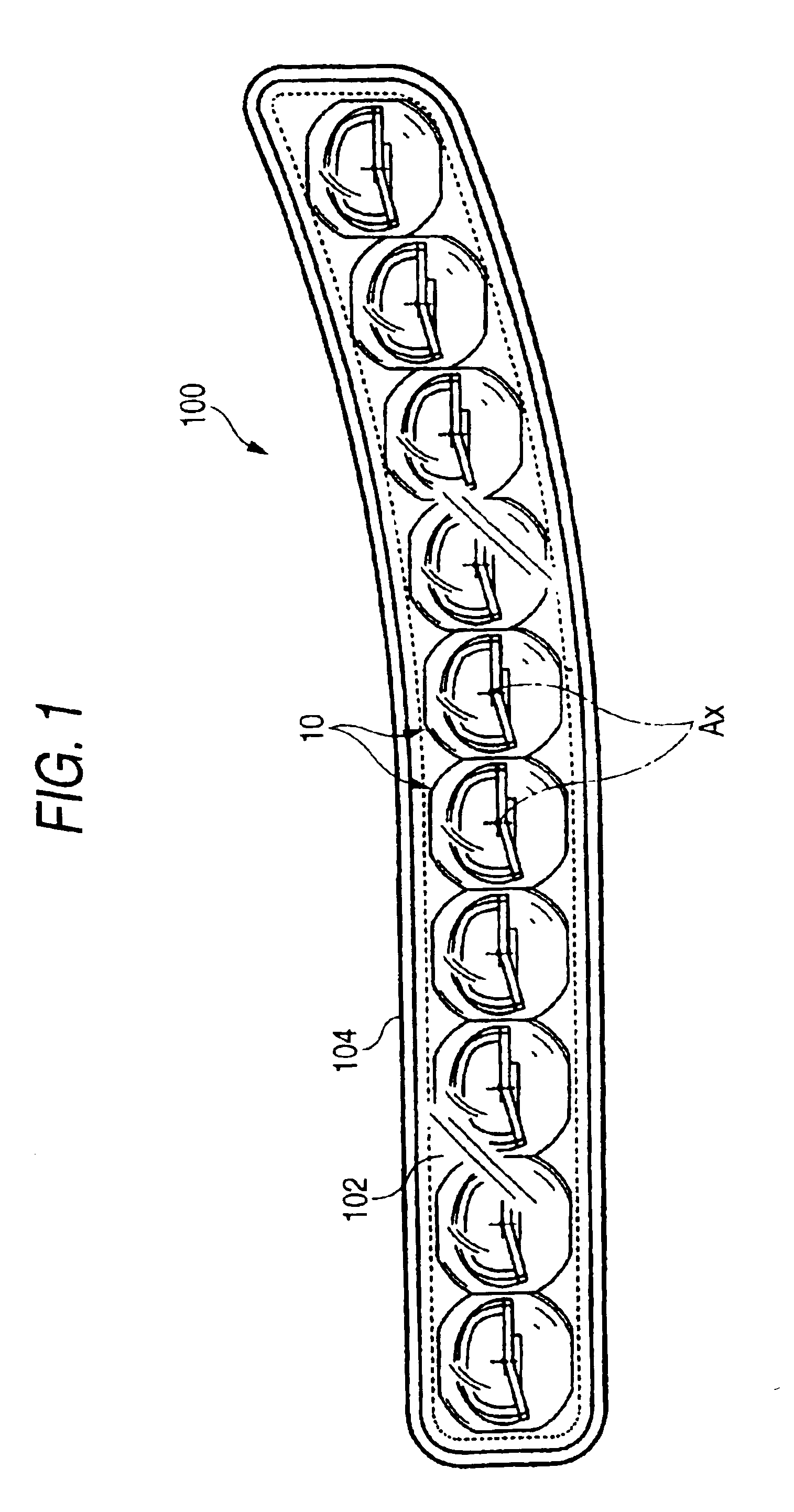
[0043]FIG. 1 is a front view showing a vehicular lamp 100 which incorporates a light source unit 10 constructed according to the invention.
[0044]The vehicular lamp, or lighting unit, 100 is a low-beam headlamp incorporating ten light source units 10 arranged in a substantially horizontal line in a lamp housing formed by a transparent cover 102 and a lamp body 104.
[0045]The light source units 10, which all have the same structure, are accommodated in the lamp housing with their optical axes Ax extending generally in the longitudinal direction of the vehicle, more specifically, in a downward direction by approximately 0.5 to 0.6 degree with respect to the longitudinal direction of the vehicle.
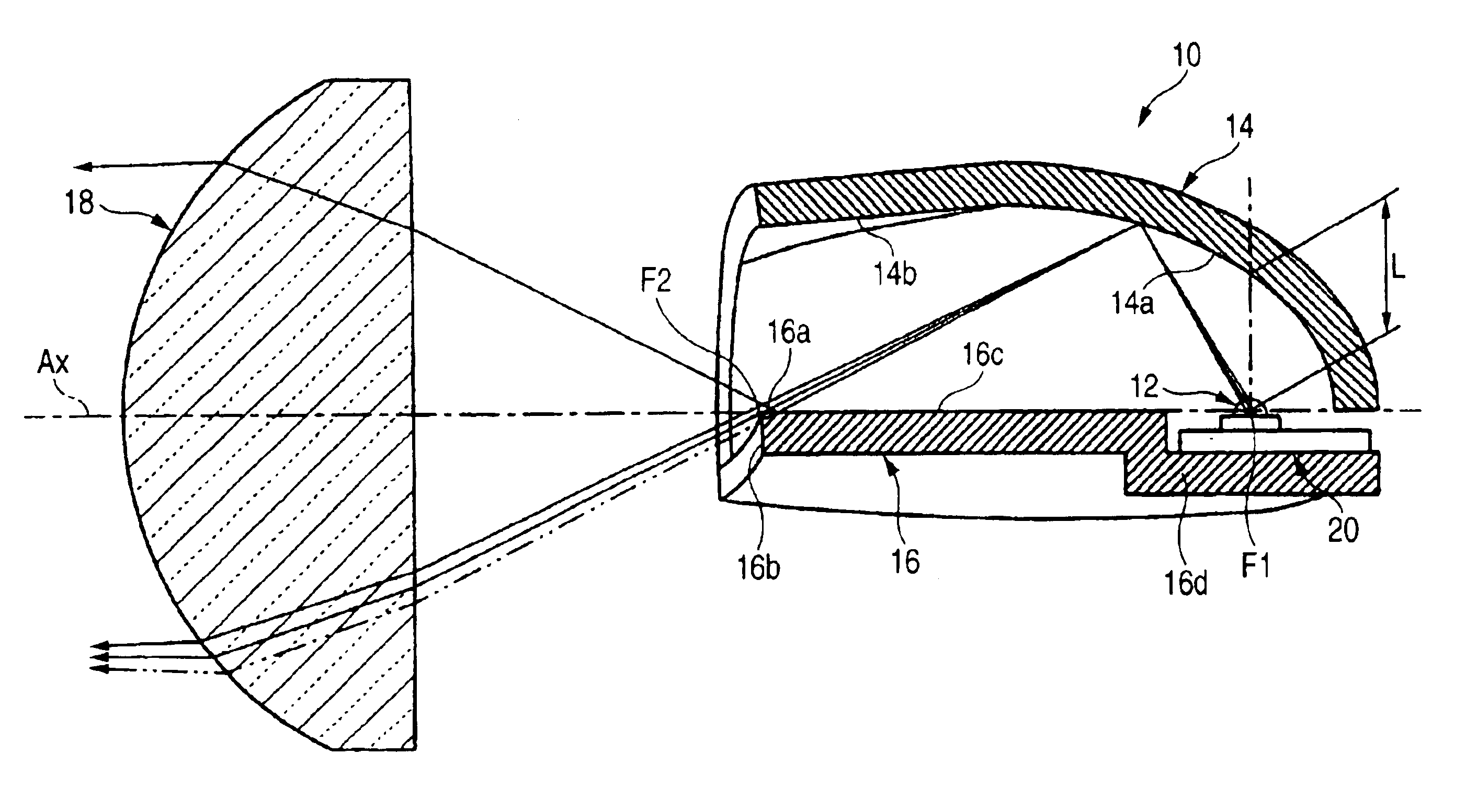
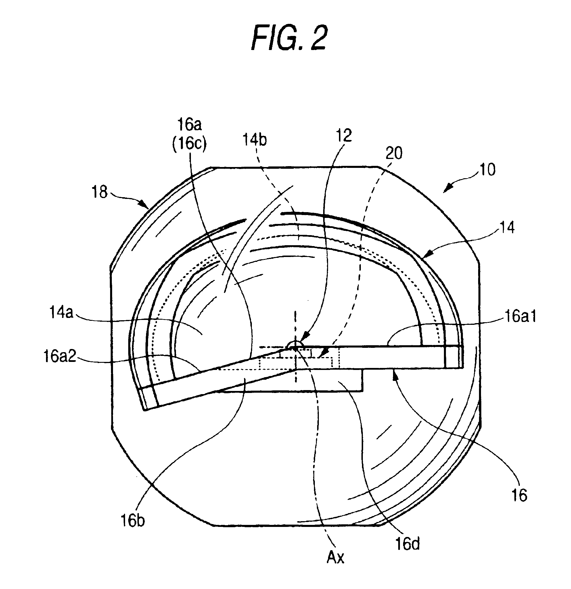
[0046]FIG. 2 is a front view showing a single light source unit 10, and FIGS. 3 and 4 are sectional side and plan views, respectively, of the light source unit 10.
[0047]As shown in these drawings, the light source unit 10 includes an LED 12 (a semiconductor light-emitting element) as a light sour...
second embodiment
[0079]Next, the embodiment will be described.
[0080]FIG. 8 is a sectional side view showing a light source unit 10A according to the second embodiment.
[0081]As shown in FIG. 8, the light source unit 10A employs different structures for the light control member 16A and projection lens 18A than those of the light control member 16 and the projection lens 18 according to the first embodiment, while other structures are the same as those in the first embodiment.
[0082]The shape of a front end face 16b of the light control member 16A is the same as that of the light control member 16 (indicated by a two-dot chain line in FIG. 8) of the first embodiment, while a shielding end face 16Aa is inclined slightly upward and rearward from the front end face 16b. The angle of inclination α may be approximately 1 to 10 degrees, for example.
[0083]The shielding end face 16Aa is formed so that a third reflecting surface 16Ac for reflecting the light reflected by the first reflecting surface 14a upward i...
third embodiment
[0106]Next, a light source unit of the invention will be described.
[0107]FIG. 13 is a sectional side view showing a light source unit 30 according to the third embodiment.
[0108]The light source unit 30 is designed for providing a high-beam light distribution pattern.
[0109]More specifically, the light source unit 30 according to the third embodiment is not provided with a light control member 16 as in the previously described embodiments. On the other hand, the light source unit 30 of the third embodiment has a second reflector 36 having a fourth reflecting surface 36a which extends forward and is inclined downward.
[0110]The structure of a first reflecting surface 34a is the same as that of the first reflecting surface 14a of the first embodiment, but the downward inclination angle of a second reflecting surface 34b formed at the upper part of the front end of the first reflecting surface 34a is greater than the angle of inclination of the second reflecting surface 14b of the first e...
PUM
 Abstract
Description
Claims
Application Information