Method and materials for hydraulic fracturing of wells

a technology of hydraulic fracturing and methods, applied in the field of treating wells, can solve the problems of reducing or even eliminating the benefits of long propped fractures, cracks or fractures in the face of rocks, and damage to the permeability of longer propped fractures, so as to prevent overflushing of proppant and high effective viscosity. , the effect of high effective viscosity

Inactive Publication Date: 2005-09-27
ENERPOL LLC
View PDF9 Cites 136 Cited by
  • Summary
  • Abstract
  • Description
  • Claims
  • Application Information

AI Technical Summary

Benefits of technology

[0014]Hydraulic fracturing processes employing a degradable thermoplastic are disclosed. In one embodiment, the degradable plastic may be placed in a wellbore near a formation to be fractured as a dispersed or discontinuous phase in a carrier fluid, so as to control pressure losses in the wellbore during placement. The degradable plastic is then converted to a continuous or external phase and used as the fracturing fluid to form a fracture near a wellbore, such that it has high effective viscosity in the fracture. In other embodiments, the degradable plastic may be injected into a fracture as the discontinuous or internal phase, where high effective viscosity in the fracture is not required. In most applications, at least some of the degradable plastic injected carries a proppant into the fracture. Injection of a degradable plastic phase can be used in a variety of well applications, including: forming a short fracture having length sufficient to bypass damage to permeability near a wellbore; placing proppant near a wellbore in a previously formed fracture; replacing damaged proppant near a wellbore in a previously formed fracture; preventing overflushing of proppant after a fracturing treatment; preventing flowback of proppant after a fracturing treatment; and forming a fracture, that may remain plugged for a selected time, before gravel packing or performing other completion or workover operations are performed in a well.

Problems solved by technology

This causes a crack or fracture to develop in the face of the rock at the wellbore.
Some evidence exists that conventional fracturing fluids, containing a soluble gelling polymer, damaged the permeability of the longer fractures formed with conventional fluids when gravel packing, whereas much shorter fractures formed with water appeared to be just as effective.
Even a short distance of unpropped fracture or of proppant with damaged permeability can greatly diminish or even eliminate the benefits of the long propped fracture.
Damage removal in connection with gravel packing of very high permeability formations was discussed above, but damage to flow capacity of wells in all permeability ranges is widely observed.
Well stimulation methods that are generally used for damage removal near a wellbore include limestone and sandstone acidizing and solvent injection, but often these treatments are not successful or their effectiveness quickly diminishes as fluid is produced from a well.
This method can be especially needed in remote areas, where mobilizing of materials and equipment is expensive.
But, viscosity of a fracturing fluid is normally limited by pressure loss as the fluid is pumped down a wellbore.
Another limit on increasing viscosity of present fracturing fluids is that the water-soluble polymers most commonly used do not completely degrade, but leave a residue that adversely affects flow capacity of the proppant left in a fracture.
Higher polymer concentrations in the injected fluid to produce higher viscosity and wider fractures would cause even greater damage to proppant flow capacity in the fracture.
Other viscous solutions, based on surfactant molecules, have been developed, but they have disadvantages such as the uncertainty of positive reduction of viscosity with time and high cost.
All presently used fracturing fluids have the disadvantage that large quantities of liquid must be pumped into a well because the effective viscosity of the fluid in a fracture is limited.
Difficulties in handling the oil and in controlling the process caused the process to lose favor, but the concept of using a lubricating layer in tubing to inject a viscous fracturing fluid was demonstrated.
If water was the external phase in a hydraulic fracture, viscous oil did not have high effective viscosity in the fracture, either.

Method used


Image

  • Method and materials for hydraulic fracturing of wells
  • Method and materials for hydraulic fracturing of wells
  • Method and materials for hydraulic fracturing of wells

Examples


Embodiment Construction

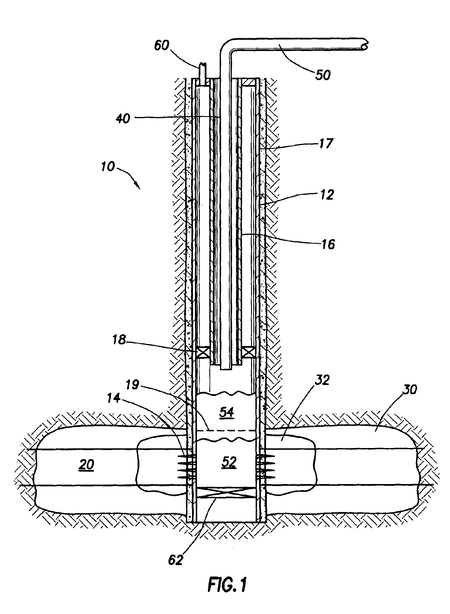
[0019]Referring to FIG. 1, wellbore 10 penetrates formation 20 where fluid is to be produced or injected. Wellbore 10 has casing 12 extending through formation 20, casing 12 being cemented in place by cement sheath 17. Perforations 14 have been formed through the wall of casing 12 and cement sheath 17 into formation 20. Perforations 14 may extend over the entire thickness of formation 20 or may extend only over a selected interval of formation 20 less than the total thickness surrounding wellbore 10. In some wells, hydraulic fracture 30 may have been formed around wellbore 10 by a previous treatment employing conventional fracturing fluid and proppant, using techniques well-known in industry. Hydraulic fracture 30 may have been formed for a time before injection of the fracturing fluid disclosed herein or may have been formed immediately before injection of the fracturing fluid disclosed herein. Alternatively, fracture 30 may not be present. Tubing 16 may have been suspended inside ...


PUM

PropertyMeasurementUnit
distancesaaaaaaaaaa
lengthaaaaaaaaaa
lengthsaaaaaaaaaa

Abstract

Hydraulic fracturing of wells by injecting a degradable polymer phase as a fracturing fluid is provided. Composition and degree of polymerization of the degradable polymer and the selection of additives may be varied to adjust the viscosity, degradation time and other properties of the fracturing fluid. Viscous degradable fluid or pellets of degradable polymer may be placed in a wellbore as an internal phase in a low viscosity carrier fluid. A polymer-continuous liquid phase may be formed at a selected location in the wellbore, usually near perforations, before the polymer phase is pressured into a formation to form a hydraulic fracture.

Description

[0001]This application claims the benefit of U.S. Provisional Application No. 60 / 325,071, filed Sep. 26, 2001, and U.S. Provisional Application No. 60 / 340,224, filed Dec. 7, 2001.BACKGROUND OF THE INVENTION[0002]1. Field of the Invention[0003]This invention pertains to treating wells to increase production rate by hydraulic fracturing. More particularly, methods are provided for increasing flow rate of wells by injecting a highly viscous material, which may be a thermoplastic degradable polymer, which may contain proppant particles, into an earth formation surrounding a well. In other embodiments, methods are provided to improve conventional hydraulic fracturing and sand control processes.[0004]2. Discussion of Related Art[0005]Hydraulic fracturing of earth formations around a wellbore for increasing fluid productivity or injectivity of the well is a mature technology. Normally, thousands of gallons of an oil-based or water-based fluid, usually made viscous by addition of a soluble ...

Claims


Application Information

Patent Timeline
Patent Type & Authority Patents(United States)
IPC IPC(8): C09K8/60C09K8/62E21B43/267E21B43/25E21B43/26
CPCC09K8/62C09K8/68E21B43/26E21B43/267Y10S507/922
Inventor COOKE, JR., CLAUDE E.
Owner ENERPOL LLC
Why Eureka
Try Eureka