Common rail supplementary atomizer for piston engines

a technology of supplementary atomizer and piston engine, which is applied in the direction of liquid fuel feeder, machine/engine, mechanical apparatus, etc., can solve the problems of unrealized anti-better results, very small coal particles, etc., and achieve the effect of rapid and compl

Inactive Publication Date: 2008-09-02
FIREY JOSEPH CARL
View PDF5 Cites 2 Cited by
  • Summary
  • Abstract
  • Description
  • Claims
  • Application Information

AI Technical Summary

Benefits of technology

[0005]A common rail supplementary atomizer, of this invention, comprises a contactor chamber, in which fuel in water slurry is contacted with atomizing gas, at a pressure well above the pressure prevailing in the cylinder gas volume of an internal combustion engine. All, or portions, of the atomizing gas dissolve into the water phase of the slurry fuel. The gas remains in solution, while the slurry remains under high pressure, through the connected common rail fuel injection system of the internal combustion engine. Slurry injection into the engine cylinder gas volume breaks up the slurry fuel into many small droplets. But each droplet contains many separate small fuel particles, and these tend to agglomerate into larger fuel particles when the water portions evaporate, prior to combustion. However, when the water phase of the slurry contains atomizing gas, dissolved at the high pressure in the contactor chamber, the injected fuel droplets will be broken apart when these dissolved gases expand out of solution, at the lower pressures in the cylinder gas volume, and the small separate fuel particles will thus be separated from each other, instead of agglomerating into fewer larger fuel particles. As a result a greater area of fuel particle surface is available for air access, and these small fuel particles are dispersed into a larger air volume. In this way the combustion of a slurry fuel will be more rapid and complete, when using a common rail supplementary atomizer of this invention, and this is one of the principal beneficial objects of this invention.
[0006]Earlier engine experiments, with coal particle in water slurry fuels, indicates that, as coal particle size was reduced, in an effort to increase the rate of combustion, these smaller particles increased the effective viscosity of the slurry, and larger slurry droplets resulted during fuel injection into the engine. Subsequent coal particle agglomeration within each droplet, created larger fuel particles with slower, and less complete, combustion. As a result, better engine performance was obtained at intermediate coal particle size, and the anticipated better results, for very small coal particles, were not realized. It is a principal beneficial object of this invention to make available the improvements of engine combustion, potentially available from the use of smaller coal particles, or smaller residual petroleum fuel particles, in fuel in water slurry fuels. Many internal combustion engine applications, currently obliged to operate on expensive distillate petroleum fuels, could operate instead on low cost residual petroleum fuels by use of the apparatus of this invention. In this way a larger portion of the crude petroleum oil could be used for our critical transportation needs.

Problems solved by technology

But each droplet contains many separate small fuel particles, and these tend to agglomerate into larger fuel particles when the water portions evaporate, prior to combustion.
As a result, better engine performance was obtained at intermediate coal particle size, and the anticipated better results, for very small coal particles, were not realized.

Method used


Image

  • Common rail supplementary atomizer for piston engines
  • Common rail supplementary atomizer for piston engines
  • Common rail supplementary atomizer for piston engines

Examples


Embodiment Construction

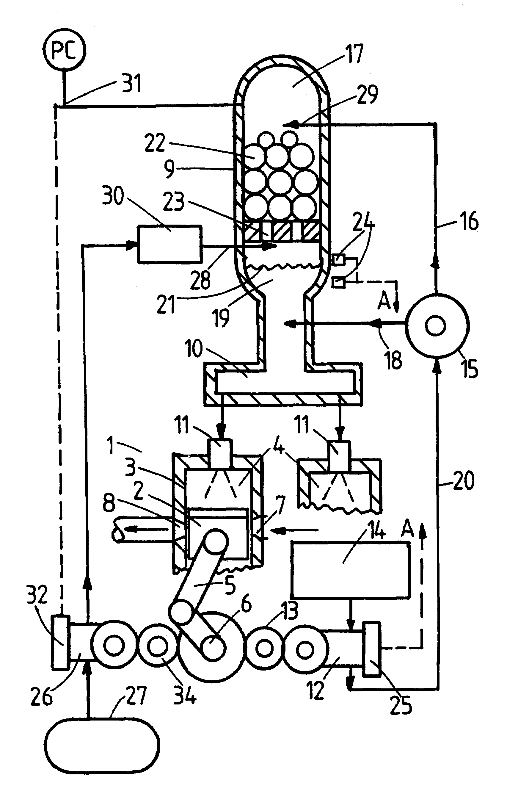
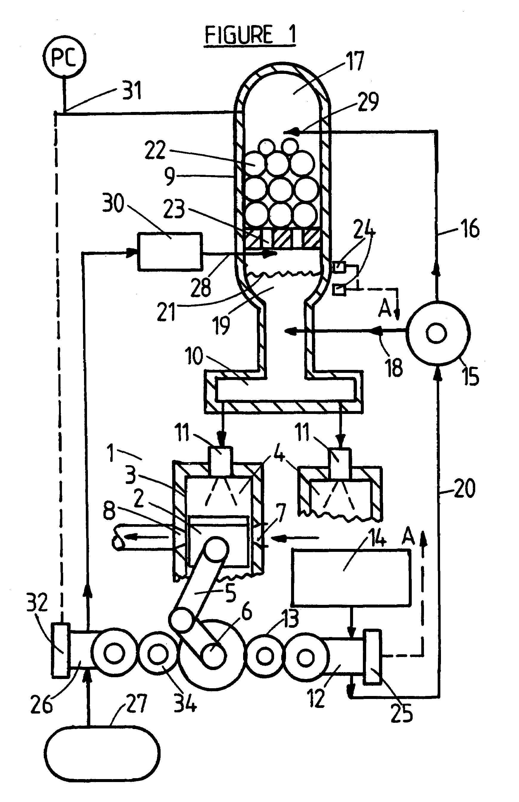
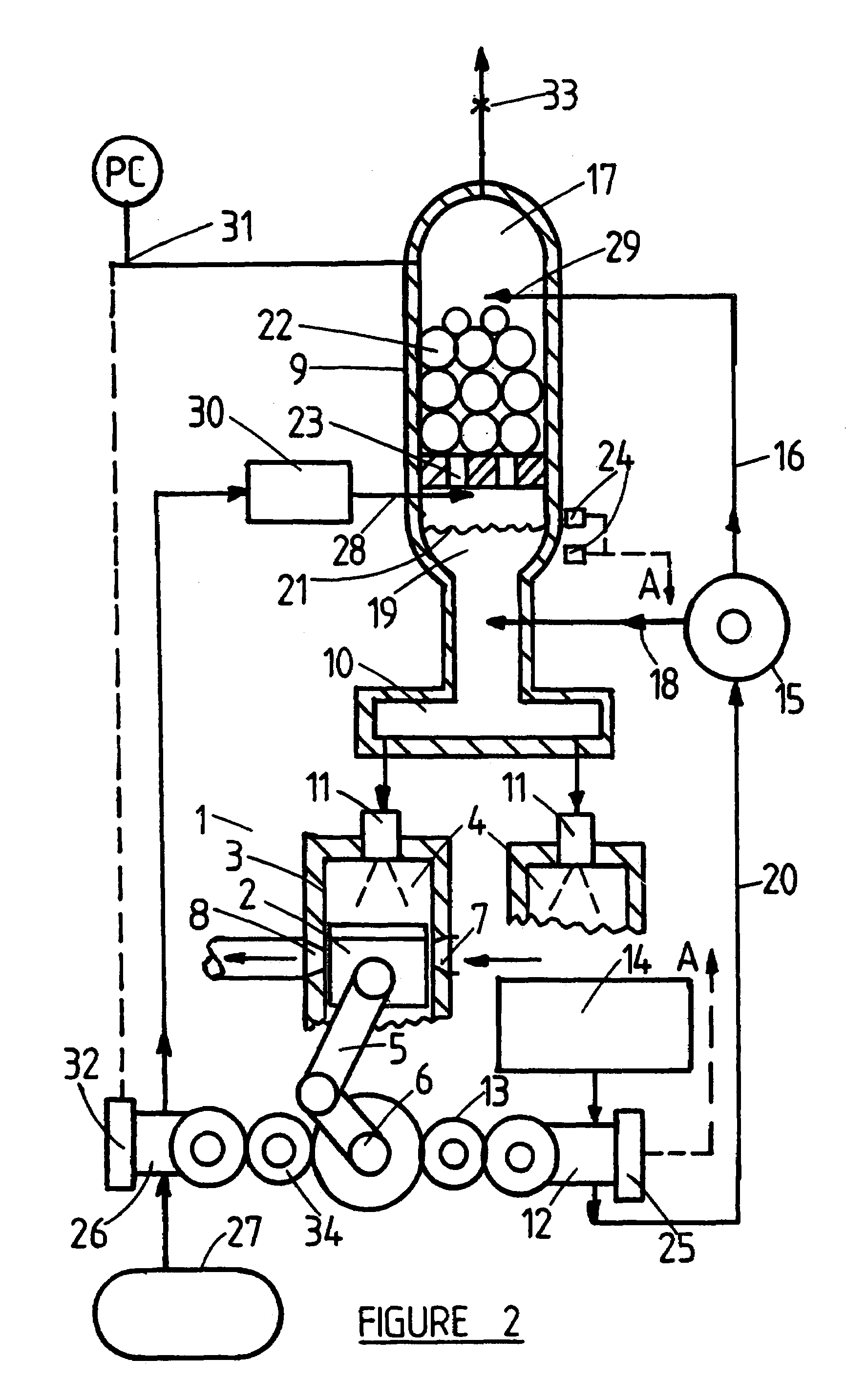
[0024]The apparatus of this invention operates to dissolve atomizing gas, at high pressure, into the liquid water portion of a fuel in water slurry, where liquid water is the continuous phase. When this gas saturated slurry is subsequently injected, into the lower pressures prevailing in the engine cylinder gas volume, these dissolved gases expand out of the water phase within each injected slurry droplet. This gas expansion between fuel particles separates the particles and prevents particle agglomeration during subsequent water evaporation, prior to fuel ignition and combustion. In this way the full benefits of fuel preatomization into very small fuel particles, suspended in a continuous water phase, can be achieved by use of the apparatus of this invention.

[0025]Various combinations of materials can be used for the suspended particle portion, and the continuous phase portion, of slurries suitable for use with the apparatus of this invention. The supplementary atomizing gas is mat...


PUM


Abstract

A common rail supplementary atomizer of this invention, when used on a piston internal combustion engine, equipped with a common rail fuel injection system, improves slurry atomization, following injection, by expansion of gases, previously dissolved in the water phase of the slurry. This gas expansion separates the several fuel particles in each slurry droplet formed first during fuel injection. The thusly separated fuel particles subsequently burn more rapidly and completely, due to this fuel particle separation improving air access to the fuel. Apparatus is described for dissolving atomizing gas into the water phase of the slurry, in a contactor chamber at a pressure greater than the pressure prevailing in the engine cylinder volume, at the time of slurry injection.

Description

CROSS REFERENCES TO RELATED APPLICATIONS[0001]The invention described herein was earlier described in my directly related Provisional U.S. patent application entitled, Common Rail Supplementary Atomizer for Piston Engines, Ser. No. 60 / 855,111, filed 30 Oct. 2006, Confirmation No. 3540. The invention described herein is also related to my following U.S. patent applications:[0002](1) Supplementary Slurry Fuel Atomizer, Provisional U.S. patent application Ser. No. 60 / 838,950, filed 21 Aug. 2006.[0003](2) Supplementary Slurry Fuel Atomizer and Supply System, U.S. patent application Ser. No. 11 / 633,107, filed 4 Dec. 2006.[0004](3) Rotary Residual Fuel Slurrifier, Provisional U.S. Patent Application Ser. No. 60 / 881,860, filed 23 Jan. 2007.This material is incorporated herein by reference thereto.SUMMARY OF THE INVENTION[0005]A common rail supplementary atomizer, of this invention, comprises a contactor chamber, in which fuel in water slurry is contacted with atomizing gas, at a pressure w...

Claims


Application Information

Patent Timeline
Patent Type & Authority Patents(United States)
IPC IPC(8): F02D19/04
CPCF02M25/0228F02M37/0064F02M55/025F02M67/00F02M25/0224F02B45/02F02B45/10F02B2275/14Y02T10/34F02M2200/24Y02T10/121Y02T10/123F02M63/0225Y02T10/12Y02T10/30
Inventor FIREY, JOSEPH CARL
Owner FIREY JOSEPH CARL
Why Eureka
Try Eureka