Thick film resistor fuel vaporizer

Inactive Publication Date: 2009-10-29
LECCA OSCAR A +2
View PDF0 Cites 7 Cited by
  • Summary
  • Abstract
  • Description
  • Claims
  • Application Information

AI Technical Summary

Benefits of technology

[0014]The fuel vaporizer in accordance with the invention is a compact construction that offers a large vaporizing surface with high-energy heaters in a small package. The fuel vaporizer is located at a position upstream of the fuel reformer and downstream of a fuel injection port. A commercially available fuel injector is well insulated from the thermal effects produced by the vaporizer and the fuel reformer is able to deliver a metered quantity of fuel as required by the reformer. The reformer's control unit may also control the fuel injector. The large heating surface of the fuel vaporizer in accordance with the invention and the high wattage capability of the thick film resistor printed or painted on the surface of the vaporizer assure the rapid and complete vaporization of the fuel injected into the vaporizer. After the vaporizing cycle is completed, a pulse of pressurized air is injected into the vaporizer cavity to purge the remaining fuel vapors preparing the space for the next vaporizing cycle by regenerating the heated surfaces.
[0015]Contrary to prior art fuel vaporizers, the fuel vaporizer in accordance with the invention provides a much simpler and more effective solution for vaporizing hydrocarbon-based fuels and, especially, diesel fuels. The fuel vaporizer in accordance with the invention has a simple construction and is easy to fabricate and assemble in automatic production lines and, therefore, more economical than prior art vaporizers. By utilizing a thick film resistor printed on the surface of the fuel vaporizer and by designing the vaporizer to have a large surface, energy is used efficiently to vaporize the fuel. The fuel vaporizer may have a modular construction and offers flexibility in operation and mounting.
[0017]In a second embodiment, the fuel vaporizer in accordance with the invention includes a plurality of heater plates, preferably discs that have a glass coated thick film resistor printed or painted on the surface. The heater plates include a plurality of holes placed in such a way that the injected fuel and generated vapors cascade from one plate to another. Accordingly, the injected fuel is contacting multiple hot surfaces in order to achieve complete vaporization of the injected fuel. The hot surfaces of the plates vaporize the fuel on contact. The design allows both sides of the heater plate to be utilized for heat transfer. Current cylindrical heaters can only utilize the inside or the outside of the heater, thus, reducing surface area while allowing heat loss to the environment.

Problems solved by technology

Traps for these contaminants, however, become sated with engine use and must be regenerated periodically.
A problem in the prior art has been how to vaporize fuel completely and uniformly, especially at start-up when the apparatus or engine is cold.
A related problem is that injected fuel droplets may follow a line-of-sight path directly to the entry surface of the catalyst, resulting in localized and sometimes extreme fuel / air inhomogeneities.
Inhomogeneous fuel / air mixtures can lead to decreased reforming efficiency and reduced catalyst durability through coke and soot formation on the catalyst and thermal degradation from local hot spots.
Poor fuel vaporization can lead to fuel puddling, resulting in uncertainty in the stoichiometry of fuel mixture.
Getting the reformer to convert diesel fuel to hydrogen, a process for which there is a substantial commercial market, involves even more challenges, since diesel fuel is difficult to vaporize.
The vaporization of diesel requires high temperatures, which lead to pyrolysis and coking (carbonaceous deposits).
The generated heat resulting from this process leads to the vaporization of the diesel fuel.
However, the grid surface is limited and, thus, the amount of fuel that can be vaporized is limited as well.
Disadvantages of this approach include, for example, that glow plugs typically are not capable of supplying sufficient power to vaporize the required amount of diesel fuel, since glow plugs do not have the required surface area to transfer the required energy.

Method used


Image

  • Thick film resistor fuel vaporizer
  • Thick film resistor fuel vaporizer
  • Thick film resistor fuel vaporizer

Examples


Embodiment Construction

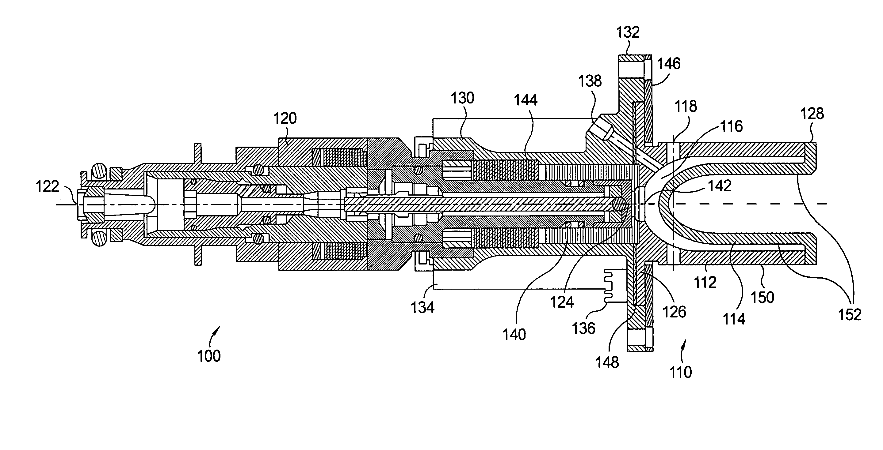
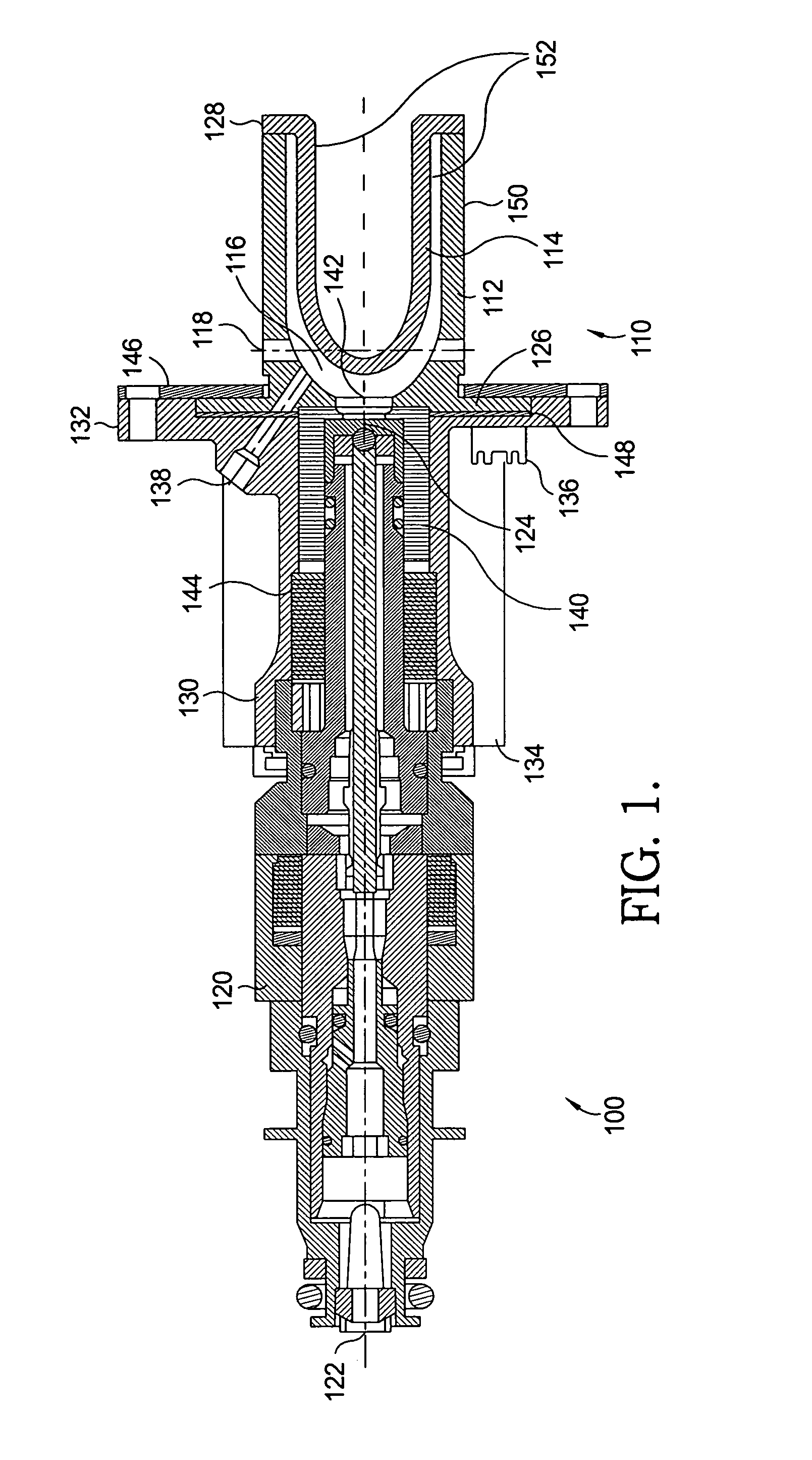
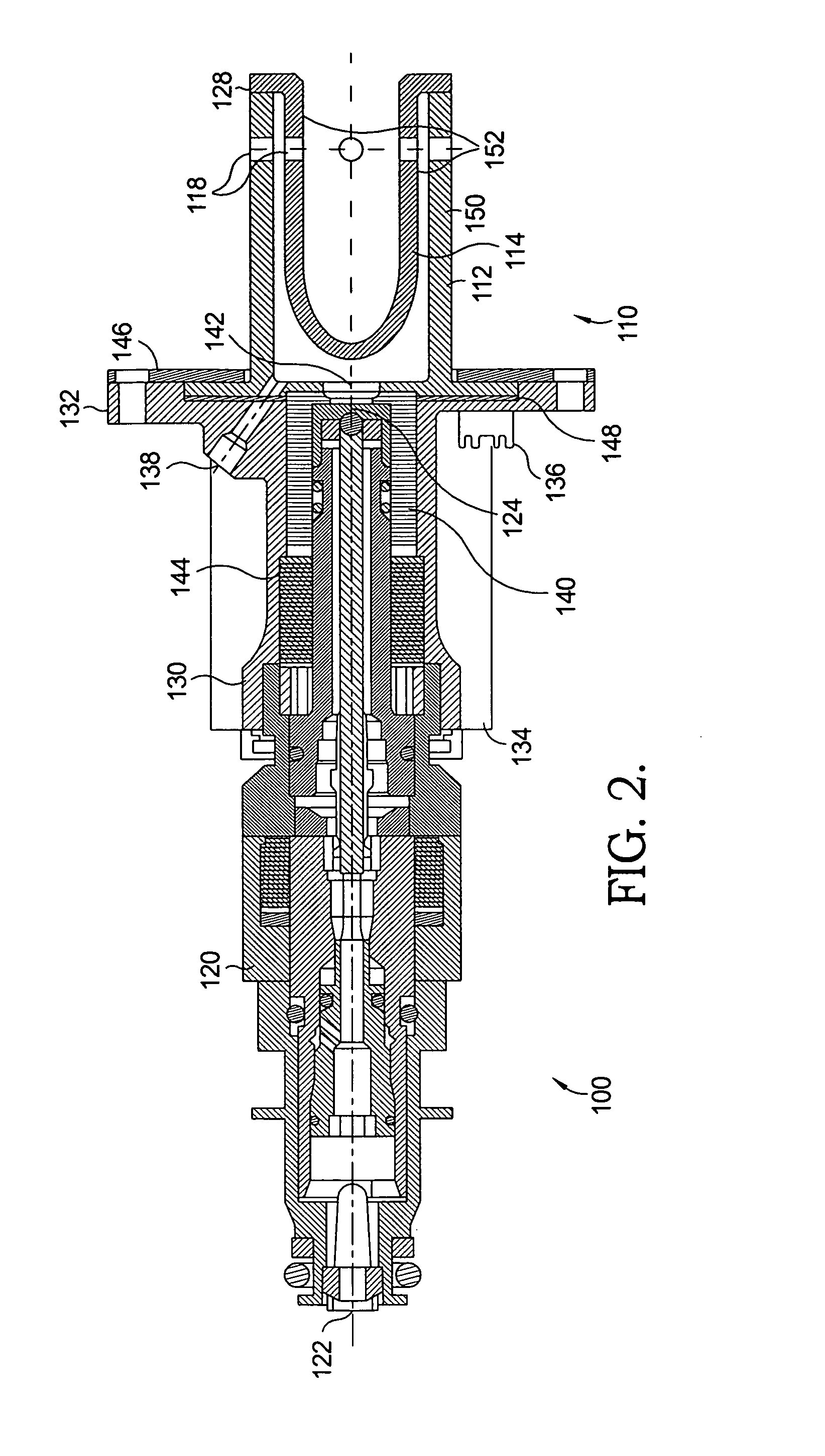
[0030]While this invention is described in the context of a diesel fuel vaporizer that provides vaporized diesel fuel to be used in an exhaust after-treatment process of a diesel type internal combustion engine that includes a hydrogen reformer system, it should be understood that the fuel vaporizer as described below may be utilized for vaporization of any hydrocarbon-based fuel for a variety of applications, including, but not limited to, fueling a solid-oxide fuel cell system and spark-ignited or diesel engines, and may further be utilized for vaporizing any liquid for use in a subsequent process.

[0031]Referring to FIGS. 1 and 2, a first fuel vaporizer assembly 100 in accordance with the invention includes a first fuel vaporizer 110 and a fuel injector 120, both assembled into a flanged housing 130 at opposite sides. Fuel injector 120 extends from a fuel inlet 122 to a fuel outlet 124. Fuel injector 120 is assembled into flanged housing 130 through an insulating ceramic adapter 1...


PUM


Abstract

A fuel vaporizer includes at least one surface and at least one glass coated thick film resistor applied to the at least one surface. The thick film resistor heats the surface and liquid fuel vaporizes on contact with the heated surface. By employing glass coated thick film, the fuel vaporizer provides a compact and economical solution for generating heat on a large heat transfer surface area. By integrating a temperature sensor into each heating area, the temperature of each heating area may be monitored and controlled individually. By providing multiple heated surface and multiple heater stages, rapid and complete fuel vaporization is provided. The generated fuel vapor may be used for any number of exhaust after-treatment processes, such as in exhaust fuel injection, diesel particulate filter burnout by igniting the vapor to perform fast warm-up of a nitrogen oxide absorber, or as an oxidation catalyst.

Description

TECHNICAL FIELD[0001]The present invention relates to a fuel reformer system that may be used in conjunction with internal combustion engines; more particularly, to apparatus and method for vaporizing fuel to create vapors to be used by the reformer system to produce hydrogen; and most particularly, to a thick film resistor fuel vaporizer.BACKGROUND OF THE INVENTION[0002]Diesel fuel is a conventional hydrocarbon-based fuel used worldwide. It is used, for example, in diesel type internal combustion engines and for diesel aggregates in grid-independent power supplies. In combination with a reformer for generating hydrogen, diesel is the ideal fuel for many fuel cell applications, especially for solid oxide fuel cell systems.[0003]Diesel engines typically are provided with exhaust after treatment devices to clean exhaust gases by trapping nitrogen oxides and carbon particulates formed during engine combustion. Traps for these contaminants, however, become sated with engine use and must...

Claims


Application Information

Patent Timeline
IPC IPC(8): F02M31/18F02M31/125
CPCF02M31/125Y02T10/126F02M31/18Y02T10/12
Inventor LECCA, OSCAR A.GOULETTE, DAVID A.MAIER, EUGEN
Owner LECCA OSCAR A
Why Eureka
Try Eureka