Brushless DC motor having an AC power control device

a dc motor and control device technology, applied in the direction of motor/generator/converter stopper, dynamo-electric converter control, instruments, etc., can solve the problems and achieve the effect of prolonging the useful life and reducing power consumption

Inactive Publication Date: 2005-09-27
SUNONWEALTH ELECTRIC MACHINE IND
View PDF8 Cites 20 Cited by
  • Summary
  • Abstract
  • Description
  • Claims
  • Application Information

AI Technical Summary

Benefits of technology

[0009]The primary objective of this invention is to provide a brushless dc motor having an ac control device, which includes a rectifier unit to rectifier an ac power source. The ac control device further includes a voltage-stabilizing control unit and a voltage-stabilizing unit to thereby stabilize a dc power source converted from the ac power source. The ac control device accomplishes to limit a passage of a high voltage and to allow a passage of a low voltage supplied from the dc power source into a motor drive circuit. Thereby, the brushless dc motor may reduce the power consumption and prolong the useful life.

Problems solved by technology

Thereby, the brushless dc motor may reduce the power consumption and prolong the useful life.

Method used


Image

  • Brushless DC motor having an AC power control device
  • Brushless DC motor having an AC power control device
  • Brushless DC motor having an AC power control device

Examples


Embodiment Construction

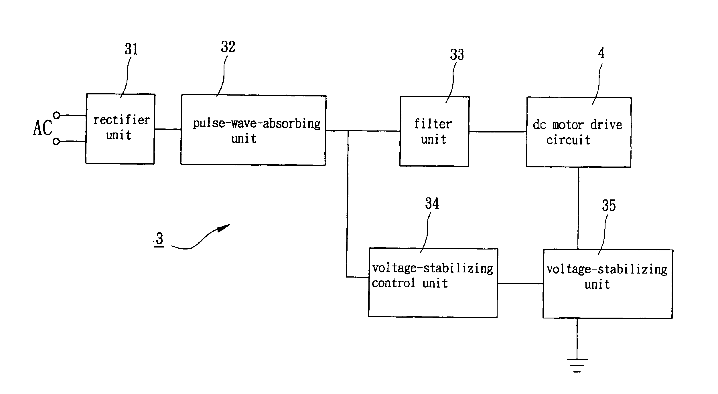
[0018]Referring to FIG. 3, it illustrates a block diagram of a brushless dc motor having an ac power control device in accordance with a preferred embodiment of the present invention. Referring to FIG. 4, it illustrates a schematic circuitry of the brushless dc motor connected with the ac power control device in accordance with the preferred embodiment of the present invention.

[0019]Referring again to FIG. 3, a brushless dc motor in accordance with the present invention include a conversion circuit 3 and a dc motor drive circuit 4. The conversion circuit 3 is serially connected between an ac power source and a dc motor drive circuit 4. The conversion circuit 3 is adapted to convert an ac voltage into a dc voltage, such as 12 V, that is suitable for the miniature brushless dc motor. The conversion circuit 3 includes a rectifier unit 31, pulse-wave-absorbing unit 32, a filter unit 33, a voltage-stabilizing control unit 34 and a voltage-stabilizing unit 35.

[0020]Referring again to FIG....


PUM


Abstract

A brushless dc motor includes a conversion circuit and a dc motor drive circuit. The conversion circuit includes a rectifier unit, a pulse-wave-absorbing unit, a filter unit, a voltage-stabilizing control unit and a voltage-stabilizing unit. The rectifier unit, the pulse-wave-absorbing unit and the filter unit are serially connected between an ac power source and the dc motor drive circuit. The ac power source is rectified, stabilized and filtered to thereby supply with a dc voltage to the dc motor drive circuit. The voltage-stabilizing control unit and the voltage-stabilizing unit are serially connected between the rectifier unit and the dc motor drive circuit so as to limit a passage of a high voltage and to allow a passage of a low voltage through the dc motor drive circuit. Thereby, the voltage-stabilizing control unit and the voltage-stabilizing unit are commonly in control of the operation of the dc motor drive circuit.

Description

BACKGROUND OF THE INVENTION[0001]1. Field of the Invention[0002]The present invention is related to a brushless dc motor having an ac control device. More particularly, the present invention is related to a brushless dc motor using a rectifier unit, a voltage-stabilizing control unit and a voltage-stabilizing unit to rectify and stabilize an ac power source.[0003]2. Description of the Related Art[0004]Referring to FIG. 1, U.S. Pat. No. 6,278,248, entitled “BRUSHLESS DC MOTOR FAN DRIVEN BY AN AC POWER SOURCE”, issued on Aug. 21, 2001 to HORNG et al, discloses a brushless dc motor fan. The brushless dc fan motor includes a converter circuit 1 consisted of a bridge rectifier 11, a resistor 12 and a filter 13. The converter circuit 1 employs the bridge rectifier 11 to convert an ac voltage into a dc voltage and to supply it to a motor drive circuit 2 and a sensor element 20. The resistor 12 is adapted to step down the dc voltage supplied from the rectifier 11 so that a step-down voltage...

Claims


Application Information

Patent Timeline
Patent Type & Authority Patents(United States)
IPC IPC(8): H02P1/18H02P6/00H02P7/00
CPCH02P6/28
Inventor HORNG, ALEXWU, WEN-CHUNGCHENG, CHUNG-KEN
Owner SUNONWEALTH ELECTRIC MACHINE IND
Why Eureka
Try Eureka