Reference voltage generating circuit for outputting multi-level reference voltage using fuse trimming

a reference voltage and generating circuit technology, applied in the direction of electric variable regulation, process and machine control, instruments, etc., can solve the problems of unstable supply voltage provided from outside the band gap device to have variation in voltage level, complicated fuse decoder and fuse box, and large number of resistors

Active Publication Date: 2005-09-27
SK HYNIX INC
View PDF19 Cites 31 Cited by
  • Summary
  • Abstract
  • Description
  • Claims
  • Application Information

AI Technical Summary

Benefits of technology

[0037]It is, therefore, a primary object of the present invention to provide a reference voltage generating circuit capable of trimming a reference voltage to various voltage levels with minimum number of resistors that are required to trim the voltage level.

Problems solved by technology

Typically, the supply voltage that is provided from outside of the band gap device is unstable to have variation in its voltage level.
However, in actual process, the reference voltage Vref is not generated as having a designed voltage level due to various process variables in most cases.
Accordingly, the fuse decoder and the fuse box get complicated.
Here, if each resistor is chosen to have a lager resistance, the number of the resistors can be reduced but the fuse trimming operation cannot be adjusted finely.

Method used


Image

  • Reference voltage generating circuit for outputting multi-level reference voltage using fuse trimming
  • Reference voltage generating circuit for outputting multi-level reference voltage using fuse trimming
  • Reference voltage generating circuit for outputting multi-level reference voltage using fuse trimming

Examples


Embodiment Construction

[0050]Hereinafter, with reference to the accompanying drawings, a preferred embodiment of the present invention will be explained in detail.

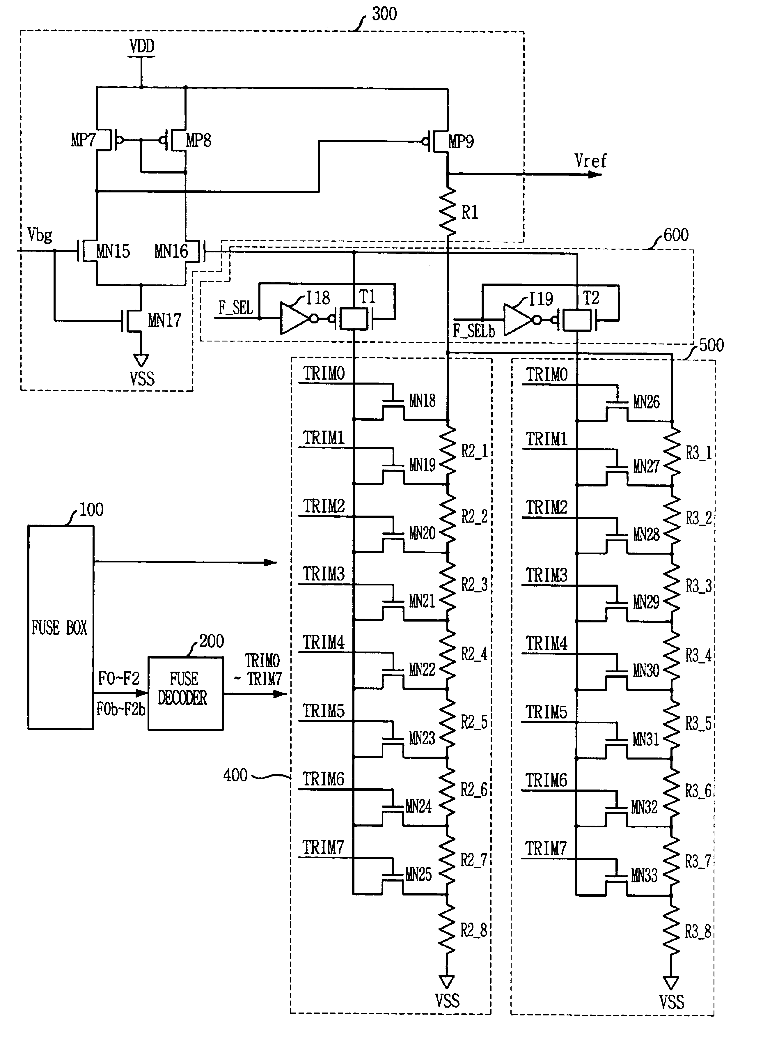
[0051]FIG. 6 illustrates a block diagram of a reference voltage generating circuit of the present invention.

[0052]Referring to FIG. 6, the reference voltage generating circuit 1000 comprises an operational amplifier 300, a first variable resistor unit 400, a second variable resistor unit 500 and a selecting unit 500. The operational amplifier 300 receives a band gap reference voltage Vbg to its positive input (+) and outputs a reference voltage Vref. The first variable resistor unit 400 has a resistor R1 having one end that is coupled to the output of the operational amplifier 300, and a plurality of resistors R2_1-R2—n that are serially coupled between the resistor R1 and a ground voltage VSS for providing the negative input of the operational amplifier 300 with a first trimming voltage Vt1 that is inputted to one end of selected one of the plu...


PUM


Abstract

A reference voltage generating circuit includes voltage outputting means for outputting a reference voltage corresponding to a difference between a band gap reference voltage and an input voltage; a first resistor having one end that is coupled to the output of the voltage outputting unit; first variable resistor unit having a plurality of second resistors that are serially coupled between the first resistor and a ground voltage, for providing the input voltage of the voltage outputting unit with a first trimming voltage that is inputted to one end of selected one of the plurality of the second resistors in response to decoded signals for trimming the reference voltage; second variable resistor having a plurality of third resistors coupled serially between the first resistor and the ground voltage, the third resistors having different resistances from the second resistors, for providing the input voltage of the voltage outputting unit with a second trimming voltage that is inputted to one end of selected one of the plurality of the third resistors in response to the decoded signals for trimming the reference voltage; and selecting unit for selectively providing the first trimming voltage or the second trimming voltage to the input voltage of the voltage outputting unit.

Description

FIELD OF THE INVENTION[0001]The present invention relates to a semiconductor memory device; and, more particularly, to a reference voltage generating circuit for outputting a reference voltage of a predetermined level in a memory device.BACKGROUND OF THE INVENTION[0002]As a semiconductor memory device gets integrated further and further, internal voltages of various voltage levels are used inside the memory such that a separate voltage is used for a core region or a higher voltage is used for over-driving operation of high speed data access, in order to reduce power consumption. A reference voltage generating circuit is to output a reference voltage for generating multi-level internal voltages for use in the memory device.[0003]Typically, a supply voltage that is supplied from outside to the memory device include variation in its voltage level. A band gap reference circuit is used to output a voltage that keeps a constant level even if it happens variation in the supply voltage. The...

Claims


Application Information

Patent Timeline
Patent Type & Authority Patents(United States)
IPC IPC(8): G05F1/46G05F1/10G11C5/14
CPCG05F1/465G11C5/14
Inventor JANG, JI-EUN
Owner SK HYNIX INC
Why Eureka
Try Eureka