Al technical title is built by PatSnap Al team. It summarizes the technical point description of the patent document.
a computer system and mouse technology, applied in the field of seeing eye mouse for a computer system, can solve the problems of destroying the advantage of attendant complexity, and achieve the effects of reducing the size of the reference frame, speeding up the tracking process, and degrading the statistical quality of the correlations
Inactive Publication Date: 2005-09-27
HEWLETT PACKARD DEV CO LP +1
View PDF62 Cites 94 Cited by
Summary
Abstract
Description
Claims
Application Information
AI Technical Summary
This helps you quickly interpret patents by identifying the three key elements:
Problems solved by technology
Method used
Benefits of technology
[0008]IR light reflected from the micro textured surface is focused onto a suitable array (say, 16×16 or 24×24) of photo detectors. The LED may be continuously on with either a steady or variable amount of illumination servoed to maximize some aspect of performance (e.g., the dynamic range of the photo detectors in conjunction with the albedo of the work surface). Alternatively, a charge accumulation mechanism coupled to the photo detectors may be “shuttered” (by current shunting switches) and the LED pulsed on and off to control the exposure by servoing the average amount of light. Turning the LED off also saves power; an important consideration in battery operated environments. The responses of the individual photo detectors are digitized to a suitable resolution (say, six or eight bits) and stored as a frame into corresponding locations within an array of memory. Having thus given our mouse an “eye”, we are going to further equip it to “see” movement by performing comparisons with successive frames.
[0012]It would be desirable if a given reference frame could be re-used with successive sample frames. At the same time, each new collection of nine (or twenty-five) correlation values (for collections at t1, ti+1, etc.) that originates from a new image at the photo detectors (a next sample frame) should contain a satisfactory correlation. For a hand held mouse, several successive collections of comparison frames can usually be obtained from the (16×16) reference frame taken at t0. What allows this to be done is maintaining direction and displacement data for the most recent motion (which is equivalent to knowing velocity and time interval since the previous measurement). This allows “prediction” of how to (permanently!) shift the collection of pixels in the reference frame so that for the next sample frame a “nearest neighbor” can be expected to correlate. This shifting to accommodate prediction throws away, or removes, some of the reference frame, reducing the size of the reference frame and degrading the statistical quality of the correlations. When an edge of the shifted and reduced reference frame begins to approach the center of what was the original reference frame it is time to take a new reference frame. This manner of operation is termed “prediction” and could also be used with comparison frames that are 5×5 and an extended “near neighbor” (null, two over / one up, one over / two up, one over / one up, two over, one over, . . . ) algorithm. The benefits of prediction are a speeding up of the tracking process by streamlining internal correlation procedure (avoiding the comparison of two arbitrarily related 16×16 arrays of data) and a reduction of the percentage of time devoted to acquiring reference frames.
Problems solved by technology
Larger trial shifts are possible, of course (e.g., two over and one down), but at some point the attendant complexity ruins the advantage, and it is preferable to simply have a sufficiently high frame rate with small trial shifts.
Method used
Image
Click on the blue label to locate the original text in one second.
Reading with bidirectional positioning of images and text.
Examples
Embodiment Construction
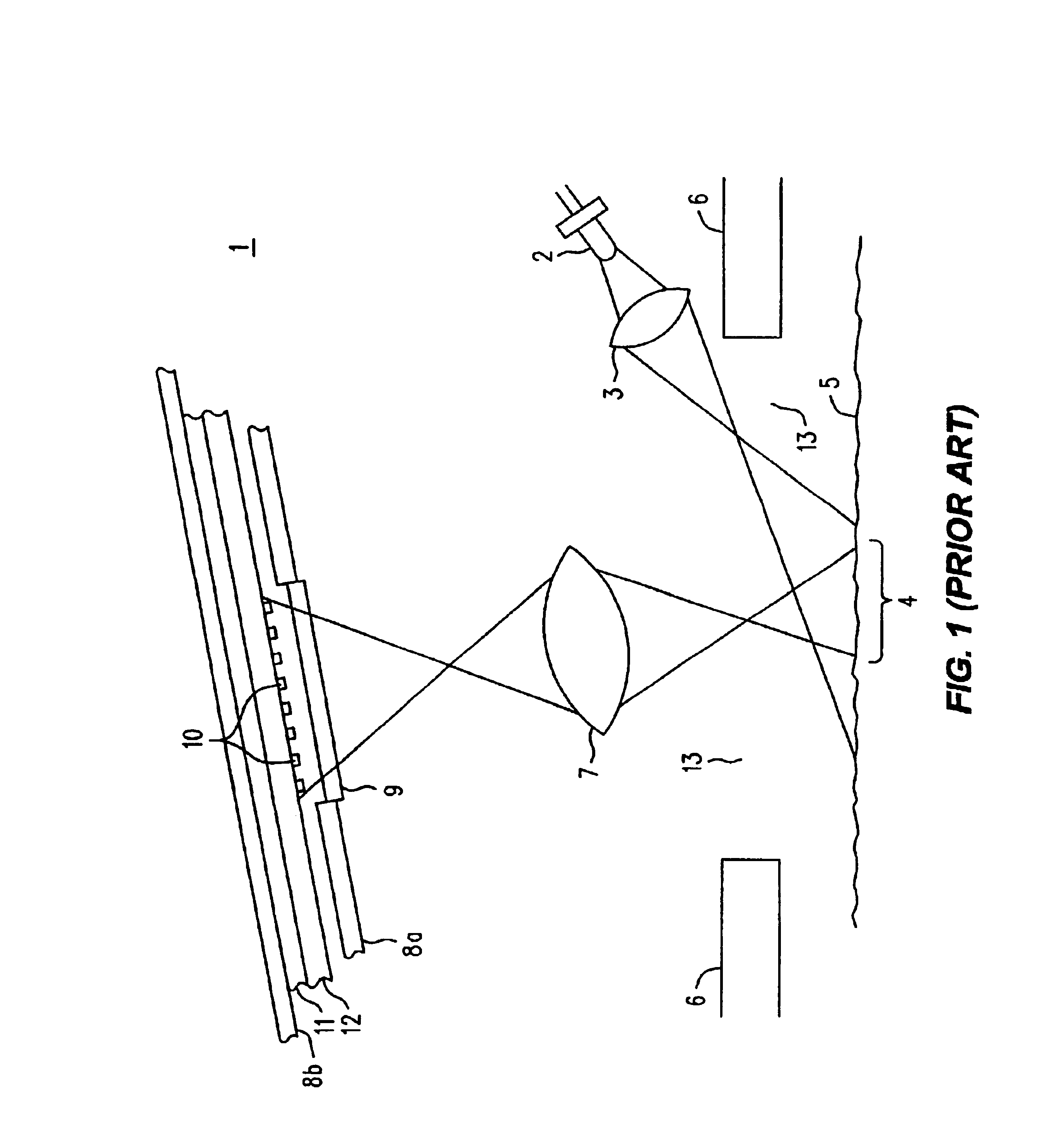
[0027]Refer now to FIG. 1, wherein is shown a simplified representation of a cut-away side view of a prior art imaging and navigation arrangement 1 that is generally of the type described by the incorporated Patents. An LED 2, which may be an IR LED, emits light which is projected by lens 3 (which instead of being separate may be an integral part of the LED's package), through orifice 13 in bottom surface 6 and onto a region 4 that is part of a work surface 5. The average angle of incidence is preferably within the range of five to twenty degrees. Although it has been omitted for clarity, the orifice 13 might include a window that is transparent for the light from LED 2, and which would serve to keep dust, dirt or other contamination out of the innards of the seeing eye mouse. Work surface 5 might belong to a special object, such as a mouse pad, or more generally, it will not, and might be the surface of nearly anything except smooth glass. Examples of suitable materials include, bu...
PUM
Abstract
An optical mouse images as an array of pixels the spatial features of generally any micro textured or micro detailed work surface below the mouse. The photo detector responses are digitized and stored as a frame into memory. Motion produces successive frames of translated patterns of pixel information, which are compared by autocorrelation to ascertain the direction and amount of movement. A hold feature suspends the production of movement signals to the computer, allowing the mouse to be physically relocated on the work surface without disturbing the position on the screen of the pointer. This may be needed if the operator runs out of room to physically move the mouse further, but the screen pointer still needs to go further. The hold feature may be implemented with an actual button, a separate proximity detector or by detecting the presence of a characteristic condition in the digitized data, such as loss of correlation or velocity in excess of a selected limit. A convenient place for an actual hold button is along the sides of the mouse near the bottom, where the thumb and the opposing ring finger grip the mouse. The gripping force used to lift the mouse engages the hold function. Hold may incorporate a brief delay upon either the release of the hold button, detection of proper proximity or the return of reasonable digitized values. During that delay any illumination control or AGC servo loops stabilize. A new reference frame is taken prior to the resumption of motion detection.
Description
CROSS REFERENCE TO RELATED APPLICATION[0001]This application is a continuation of application Ser. No. 09 / 753,805, filed Jan. 2, 2001, which will issue on Aug. 13, 2002 as U.S. Pat. No. 6,433,780, which is a continuation of Ser. No. 09 / 052,046 filed Mar. 30, 1998 U.S. Pat. No. 6,281,882, issued on Aug. 28, 2001.REFERENCE TO RELATED PATENTS[0002]This Application is related to the subject matter described in the following two U.S. Pat. Nos. 5,578,813 filed Mar. 2, 1995, issued Nov. 26, 1996 and entitled FREEHAND IMAGE SCANNING DEVICE WHICH COMPENSATES FOR NON-LINEAR MOVEMENT; and U.S. Pat. No. 5,644,139, filed Aug. 14, 1996, issued Jul. 1, 1997 and entitled NAVIGATION FOR DETECTING MOVEMENT OF NAVIGATION SENSORS RELATIVE TO AN OBJECT. Both of these Patents have the same inventors: Ross R. Allen, David Beard, Mark T. Smith and Barclay J. Tullis, and both Patents are assigned to Hewlett-Packard Co. This application is also related to the subject matter described in U.S. Pat. No. 5,786,8...
Claims
Application Information
Patent Timeline
Application Date:The date an application was filed.
Publication Date:The date a patent or application was officially published.
First Publication Date:The earliest publication date of a patent with the same application number.
Issue Date:Publication date of the patent grant document.
PCT Entry Date:The Entry date of PCT National Phase.
Estimated Expiry Date:The statutory expiry date of a patent right according to the Patent Law, and it is the longest term of protection that the patent right can achieve without the termination of the patent right due to other reasons(Term extension factor has been taken into account ).
Invalid Date:Actual expiry date is based on effective date or publication date of legal transaction data of invalid patent.