Cleating features to improve adhesive interface between an actuator tang and a tang-supporting surface of an actuator assembly of a hard disk drive

Inactive Publication Date: 2005-09-27
WESTERN DIGITAL TECH INC
View PDF5 Cites 48 Cited by
  • Summary
  • Abstract
  • Description
  • Claims
  • Application Information

AI Technical Summary

Benefits of technology

[0011]One or more of the cleating features may define a through bore configured to allow the layer of adhesive to flow therethrough. The through bore may defines a through bore axis that is substantially parallel to the pivot axis or may define a through bore axis that is substantially perpendicular to the pivot axis, other orientations being possible. One or more of the cleating features may define a nonzero elevation toward the tang. Alternatively or in addition, one or more of the cleating features may define a nonzero recess away from the tang.
[0012]According to further embodiments thereof, the present invention may also be regarded as a head stack assembly for reading and writing to a disk of a disk drive, the disk drive including a latch assembly that includes a magnet, the head stack assembly comprising a body portion defining a through bore that defines a pivot axis; an actuator arm cantilevered from the body portion; a head gimbal assembly coupled to the actuator arm; a coil portion cantilevered from the body portion in an opposite direction from the actuator arm, the coil portion defining first and second actuator fork members, one of the first and second actuator fork members defining a tang-supporting surface, the tang-supporting surface defining at least one cleating feature configured to increase a surface area of the tang-supporting surface, and a tang configured to interact with the magnet, the tang being attached to the tang-supporting surface by a layer of adhesive disposed on the tang-supporting surface.
[0013]One or more of the cleating features may define a through bore configured to allow the layer of adhesive to flow therethrough and/or may define a through bore axis that is substantially parallel to the pivot axis or may define a through bore axis that is substantially perpendicular to the pivot axis, other orientations being possible. One or more of the cleating features may define a nonzero elevation toward the tang and/or may define nonzero recess away from the tang.
[0014]Other embodiments of the present invention may also be viewed as an actuator assembly for a disk drive, the disk drive having a latch assembly that includes a magnet, the actuator assembly comprising a body portion defining a through bore that defines a pivot axis; an actuator arm cantilevered from the body portion; a coil portion cantilevered from

Problems solved by technology

Understandably, such drives may be relatively sensitive to shocks occasioned by mishandling, excessive vibrations, drops and other events causing a rapid acceleration of the disk drive.
This problem is particularly acute when the disk includes an outermost layer of glass.
As the glass surface is highly polished, there is then a great amount of contact surface

Method used


Image

  • Cleating features to improve adhesive interface between an actuator tang and a tang-supporting surface of an actuator assembly of a hard disk drive
  • Cleating features to improve adhesive interface between an actuator tang and a tang-supporting surface of an actuator assembly of a hard disk drive
  • Cleating features to improve adhesive interface between an actuator tang and a tang-supporting surface of an actuator assembly of a hard disk drive

Examples


Embodiment Construction

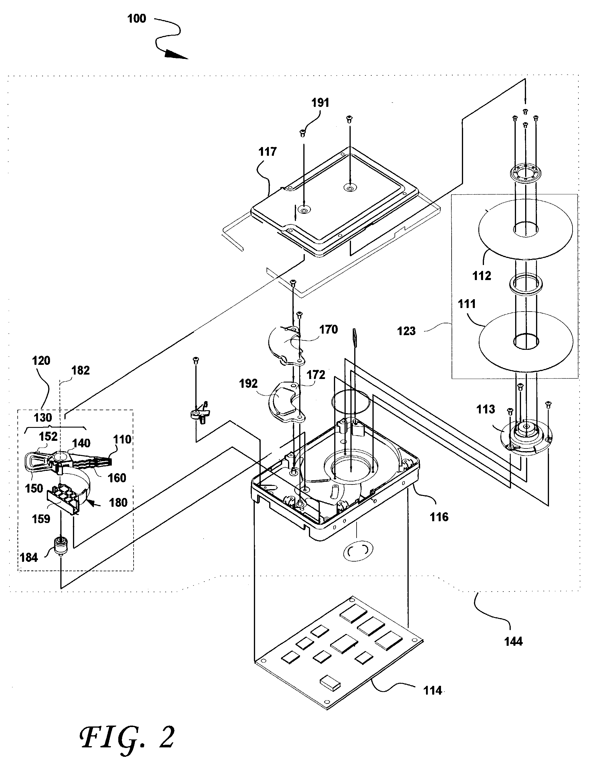
[0030]FIG. 2 shows the principal components of a magnetic disk drive 100 constructed in accordance with the present invention. With reference to FIG. 2, the disk drive 100 comprises a head disk assembly (HDA) 144 and a printed circuit board assembly (PCBA) 114. The HDA 144 includes a base 116 and a cover 117 attached to the base 116 that collectively house a disk stack 123 that includes a single magnetic disk or a plurality of magnetic disks (of which only a first disk 111 and a second disk 112 are shown), a spindle motor 113 attached to the base 116 for rotating the disk stack 123, a head stack assembly (HSA) 120, and a pivot bearing cartridge 184 that rotatably supports the HSA 120 on the base 116. The spindle motor 113 rotates the disk stack 123 at a constant angular velocity. The HSA 120 comprises a swing-type or rotary actuator assembly 130, at least one head gimbal assembly (HGA) 110, and a flex circuit cable assembly 180. The rotary actuator assembly 130 includes a body porti...


PUM


Abstract

A disk drive includes a disk, a latch assembly including a magnet and a head stack assembly for reading and writing to the disk. The head stack assembly includes a body portion defining a through bore that defines a pivot axis; an actuator arm cantilevered from the body portion; a head gimbal assembly coupled to the actuator arm; a coil portion cantilevered from the body portion in an opposite direction from the actuator arm, the coil portion defining first and second actuator fork members, one of the first and second actuator fork members defining a tang-supporting surface, the tang-supporting surface defining at least one cleating feature configured to increase a surface area of the tang-supporting surface, and a tang configured to interact with the magnet, the tang being attached to the tang-supporting surface by a layer of adhesive disposed on the tang-supporting surface.

Description

BACKGROUND OF THE INVENTION[0001]1. Field of the Invention[0002]This invention relates to magnetic disk drives. In particular, embodiments of the present invention relate to disk drives, head stack assemblies and actuator arm assemblies that include a tang supporting surface that includes one or more cleating features that increase the surface area thereof.[0003]2. Description of the Prior Art and Related Information[0004]A typical hard disk drive includes a head disk assembly (“HDA”) and a printed circuit board assembly (“PCBA”). The HDA includes at least one magnetic disk (“disk”), a spindle motor for rotating the disk, and a head stack assembly (“HSA”) that includes a slider with at least one transducer or read / write element for reading and writing data. The HSA is controllably positioned by a servo system in order to read or write information from or to particular tracks on the disk. The typical HSA has three primary portions: (1) an actuator assembly that moves in response to t...

Claims


Application Information

Patent Timeline
IPC IPC(8): G11B21/22G11B5/55G11B5/48
CPCG11B5/4813G11B5/5526
Inventor LIN, CHEN-CHI
Owner WESTERN DIGITAL TECH INC
Why Eureka
Try Eureka