
Backscatter imaging using Hadamard transform masking

a technology of masking and backscatter imaging, applied in the field of backscatter imaging, can solve the problems of extensive radiation shielding requirements, high electrical power requirements for x-ray generation, and degrading portability and self-contention

Active Publication Date: 2005-09-27
THE BOEING CO
View PDF40 Cites 29 Cited by
  • Summary
  • Abstract
  • Description
  • Claims
  • Application Information

AI Technical Summary

Benefits of technology

The method significantly enhances x-ray fluence at the target, achieving a five-order magnitude increase in incident x-ray flux without additional thermal management or information degradation, facilitating a portable and efficient backscatter imaging system.

Problems solved by technology

The collimation methods employed in these systems for scanning the x-ray beam over the target preclude the development of a portable, operationally convenient x-ray camera for on-site examination of large structures.
For mechanical collimation schemes, these conflicting requirements result in high electrical power requirements for x-ray generation and extensive radiation shielding requirements degrading both portability and self-containment.

Method used


Image

  • Backscatter imaging using Hadamard transform masking
  • Backscatter imaging using Hadamard transform masking
  • Backscatter imaging using Hadamard transform masking

Examples


Embodiment Construction

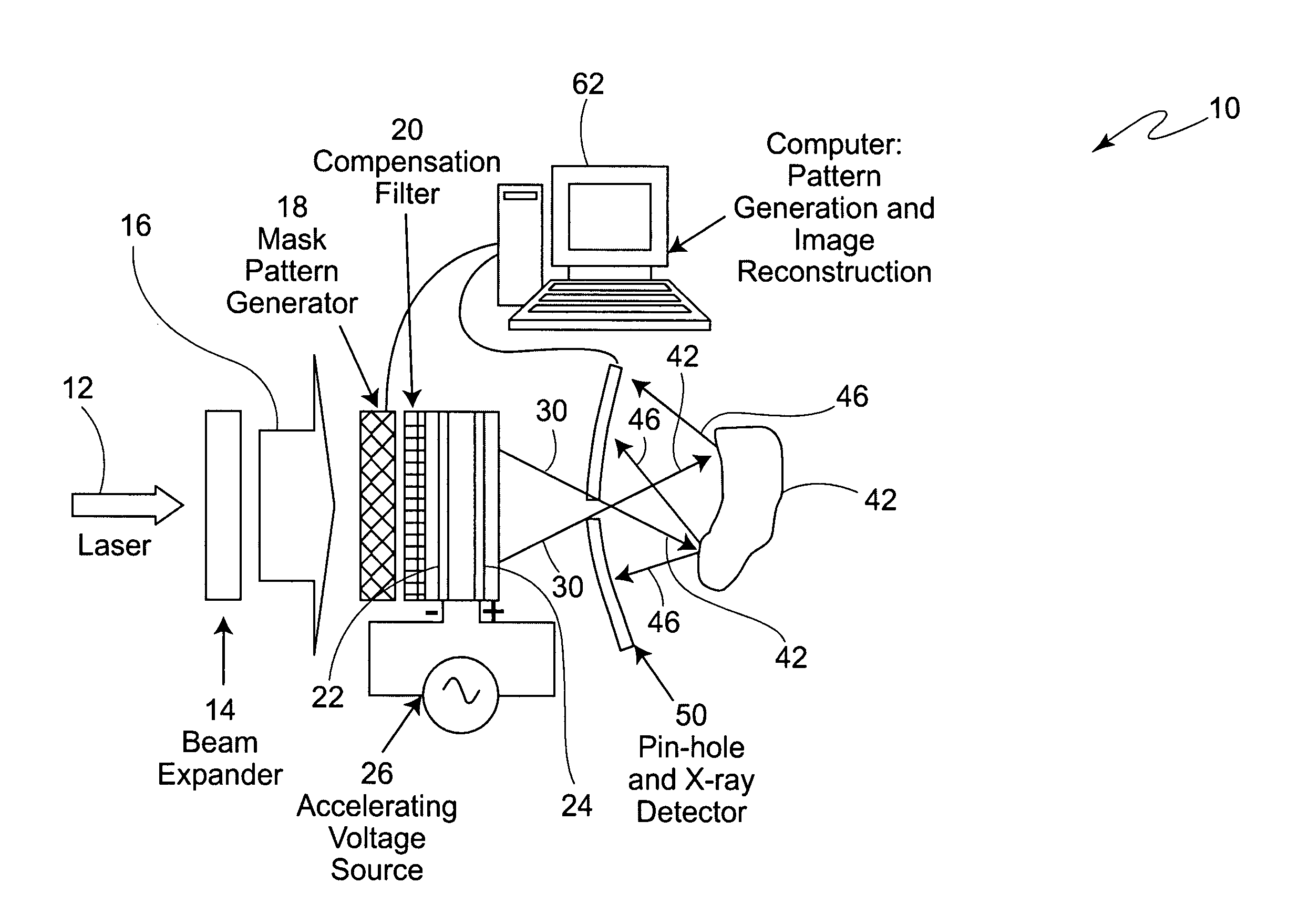
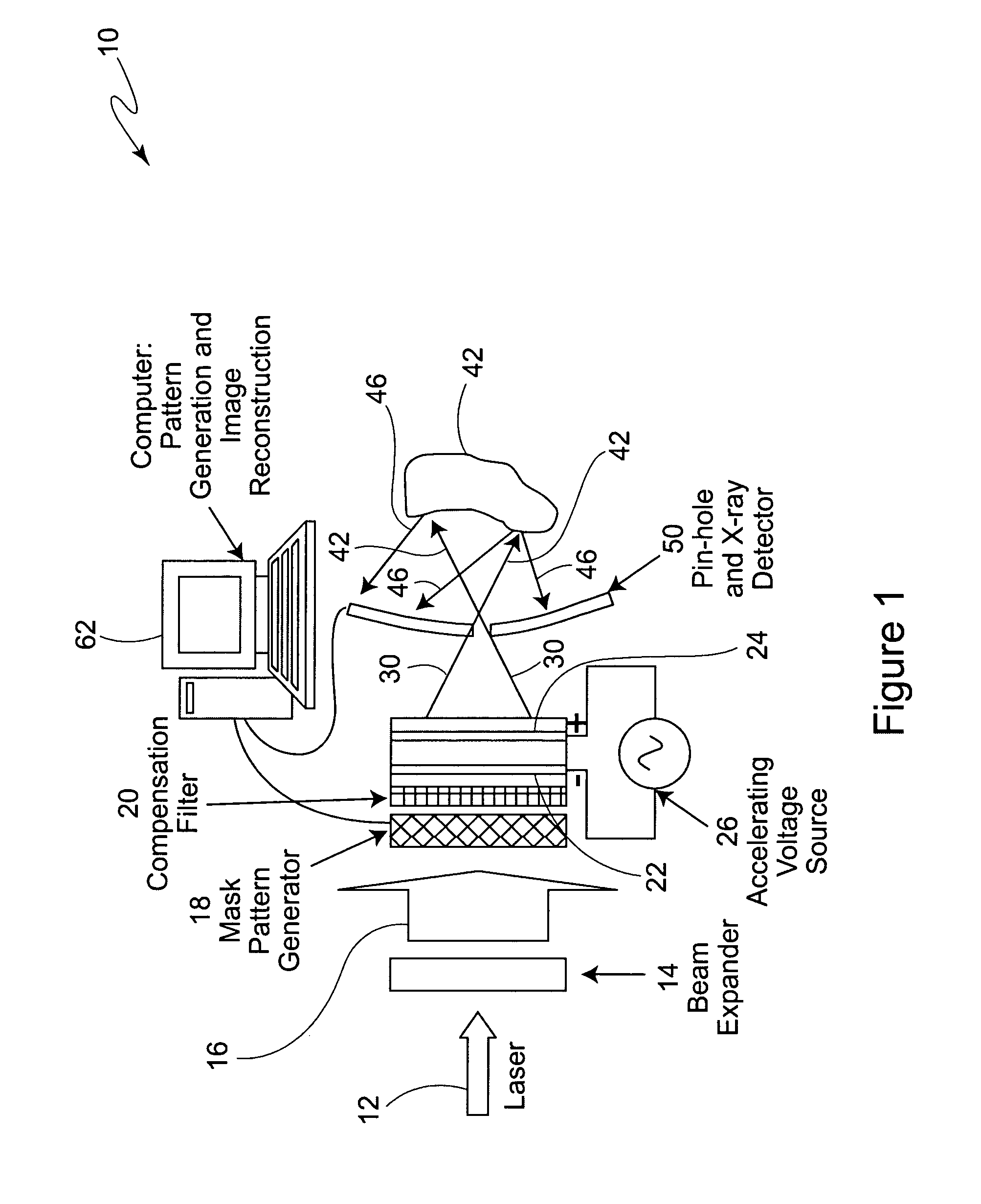
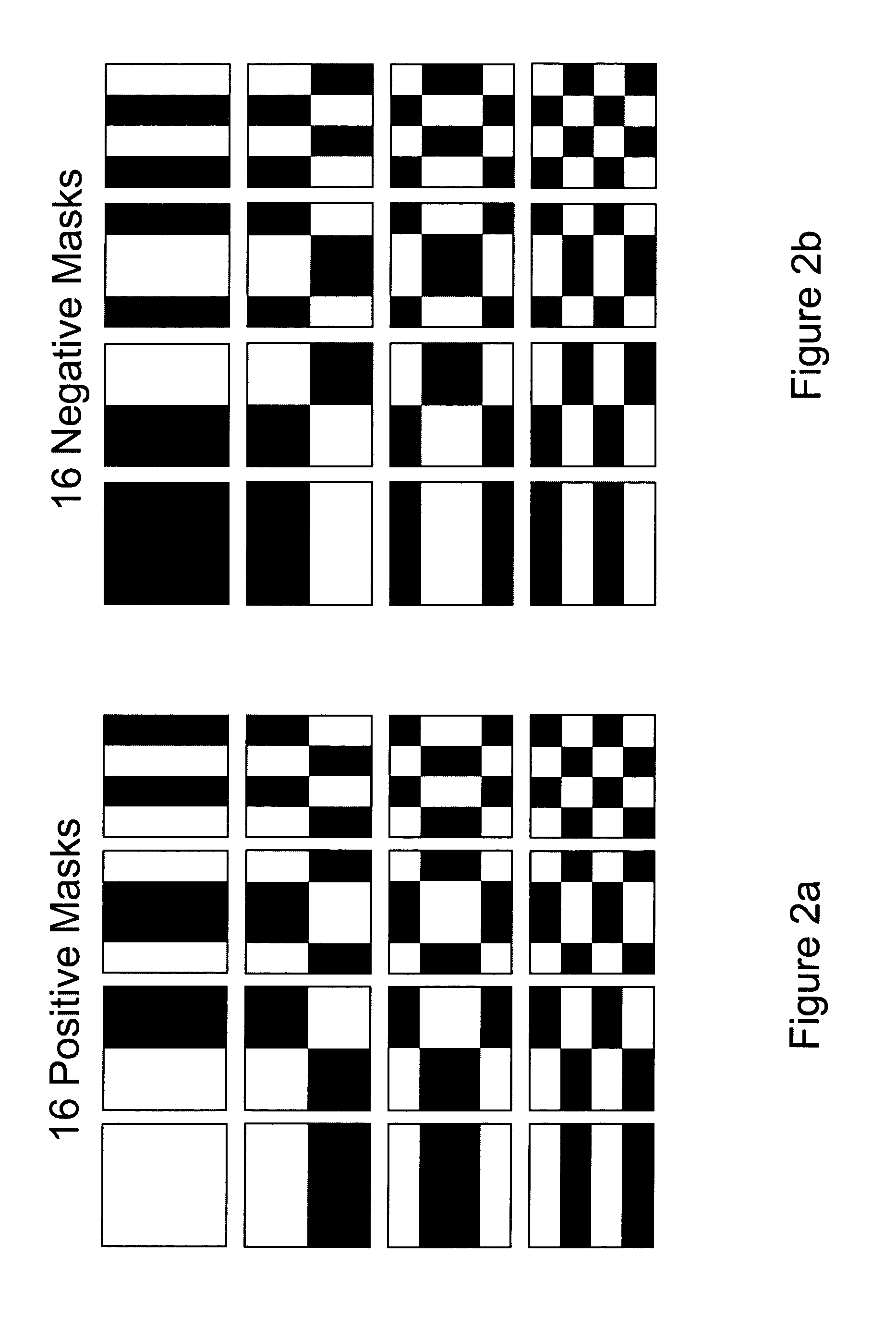
[0008]The invention comprises a Hadamard transform masking method for sequentially illuminating a backscatter target with a series of spatially modulated complete, binary valued (on or off) x-ray patterns, or other radiation source patterns, in such a way that the image of the object can be reconstructed from the backscatter signal response at a single large area detector. While the invention has particular application for backscatter x-ray imaging, it is to be understood that it has other applications as well, including, for example, for optical, IR, acoustic, and other one-sided backscatter imaging applications.

[0009]In accordance with a preferred embodiment of the invention, a source of uniform illumination is provided to some form of modulation device that masks it to produce Walsh function illumination at the surface of a large area photocathode. The intensity of the light and its color must be such as to produce photoelectron currents at each pixel sufficient to produce a requ...


PUM

PropertyMeasurementUnit
areaaaaaaaaaaa
signal strengthsaaaaaaaaaa
backscatter signal strengthsaaaaaaaaaa

Abstract

Backscatter imaging using Hadamard transform masking includes an area x-ray source with alternating, masked, Hadamard transform patterns. The total backscatter signal from a target for each pair of corresponding masks is recorded. The difference in signal strengths for each pair of corresponding masks is a direct measurement of the Hadamard transform coefficient for that mask. An image of the target is formed by performing an inverse discrete Hadamard transform on the complete matrix of coefficients.

Description

BACKGROUND OF THE INVENTION[0001]The present invention is directed to backscatter imaging, and more specifically such imaging utilizing Hadamard transform masking.[0002]One x-ray imaging approach has been Compton backscatter imaging using a flying spot x-ray source and a large x-ray detector on the same side of the target as the source. The collimation methods employed in these systems for scanning the x-ray beam over the target preclude the development of a portable, operationally convenient x-ray camera for on-site examination of large structures. This is primarily due to the competing requirements for a high x-ray fluence exposing the target at each scan position to improve signal to noise ratio for a fixed detector integration time, and the smallest possible diameter x-ray beam to improve the imaging resolution. For mechanical collimation schemes, these conflicting requirements result in high electrical power requirements for x-ray generation and extensive radiation shielding re...

Claims


Application Information

Patent Timeline
Patent Type & Authority Patents(United States)
IPC IPC(8): G01N23/20G01N23/203
CPCG01N23/203G01T1/295H01J35/00
Inventor NELSON, JAMES M.SHEPHERD, WILLIAM B.
Owner THE BOEING CO
Learn More