Image collecting device, image retrieving device, and image collecting and retrieving system

Inactive Publication Date: 2005-09-27
MITSUBISHI ELECTRIC CORP
View PDF10 Cites 112 Cited by
  • Summary
  • Abstract
  • Description
  • Claims
  • Application Information

AI Technical Summary

Benefits of technology

[0072]In the image collecting and retrieving system in accordance with the next invention, which relates to the above-mentioned invention, the image retrieving device is further provided with a collection instructing unit which gives instructions for collecting operations including the start and finish of the image collection to the image collecting device, and the image collecting device is further provided with an image collection control unit which controls the image collecting devic

Problems solved by technology

However, if there are many image pickup points and long pickup periods, the management of the recorded data becomes complicated, and the editing processes require a great amount of time and workloads.
As a result, the entire scale of the apparatus becomes larger, and it is not possible to carry out an efficient image pickup operation.
However, the positional relationship with the position and the image data to be displayed is not clarified on the map, with the result that it is not possible to positively reproduce image data representing a desired picked-up position.
Furthermore, if the user wishes to reproduce image data between desired two points, and if a plurality of sequences of image data are used for the reproducing process, a problem arises because the connection between the sequences of the image data tends to be interrupted.
Moreover, if, by using a plurality of sequences of image data, images of vehicles, etc

Method used


Image

  • Image collecting device, image retrieving device, and image collecting and retrieving system
  • Image collecting device, image retrieving device, and image collecting and retrieving system
  • Image collecting device, image retrieving device, and image collecting and retrieving system

Examples


second embodiment

[0141]A second embodiment of the present invention will now be explained. In the first embodiment, the locus C1 is displayed and outputted on the two-dimensional map as a black point so that the user can easily select and specify desired image data. However, in the second embodiment, a slide bar is displayed on the locus of a sequence of image data as a user interface so that the operability for selecting and specifying desired image data is further improved.

[0142]FIG. 5 is a block diagram that shows a construction of an image retrieving device in accordance with the second embodiment of the present invention. As shown in FIG. 5, this image retrieving device 20b is provided with a locus-type button display processing section 40 in place of the image pickup locus display processing section 32 of the first embodiment. The other structures are the same as those of the first embodiment, and the same elements are indicated by the same reference numbers. The image pickup locus display pro...

third embodiment

[0149]A third embodiment of the present invention will now be explained. In the first embodiment, only the image start point is specified by the map input section 29 so as to reproduce the image data succeeding the specified image position. However, in this third embodiment, a locus forming a route between two points specified on the two-dimensional map is displayed, and image data starting from a position specified on this route is reproduced along this route.

[0150]FIG. 7 is a block diagram that shows a construction of an image retrieving device in accordance with the third embodiment of the present invention. As shown in FIG. 7, this image retrieving device 20c has an arrangement in which a route searching section 50 is further added to the image retrieving device 20 shown in the first embodiment. The other structures are the same as those of the first embodiment, and the same elements are indicated by the same reference numbers.

[0151]Upon receipt of an start point and an end poin...

fourth embodiment

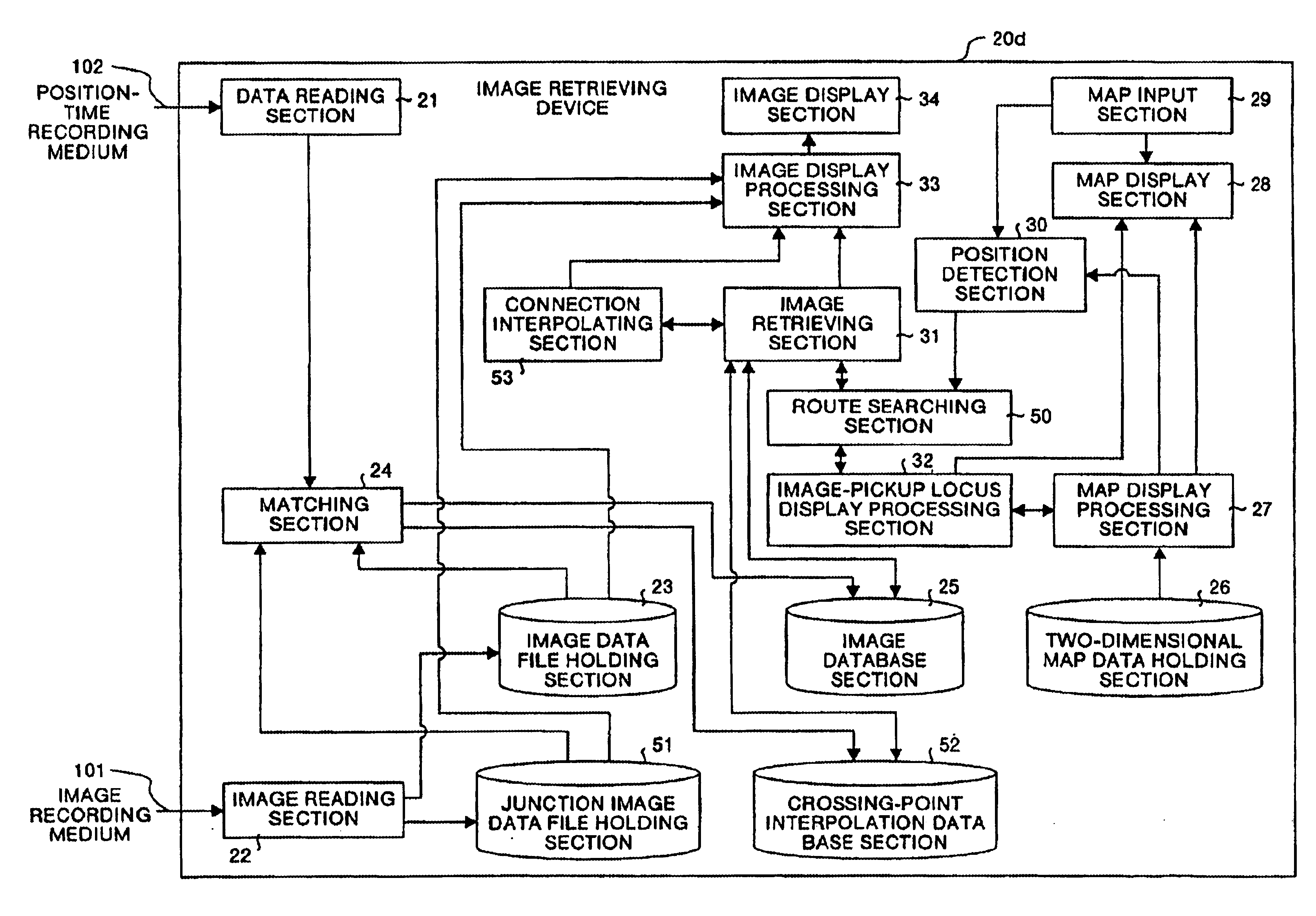
[0162]A fourth embodiment of the present invention will now be explained. In the third embodiment, when image-pickup routes of a plurality of image data files intersect each other, adjacent mage-pickup positions of the respective image-pickup data files are connected so that an image-pickup route connecting the respective image-pickup data files is formed. However, in the fourth embodiment, in order to smoothly reproduce images at the crossing point connecting the different image data file, image data of the crossing point, which has been preliminarily picked up, are used so as to interpolate the image at the time of shifting through the crossing point.

[0163]FIG. 10 is a block diagram that shows a construction of an image retrieving device in accordance with the fourth embodiment of the present invention. As shown in FIG. 10, this image retrieving device 20d is provided with a junction image data file holding section 51 for holding image data at a junction as a junction image data f...


PUM


Abstract

An image recording medium (101) and a position-time recording medium (102) are provided in an image collecting device (10). In an image retrieving device (20), a matching section (24) allows image data read from the image recording medium (101) and position-time data read by a data reading section (21) to be matched with each other based upon time so as to generate an image database. An image pickup locus display processing section (32) retrieves for image data having its image-pickup position on a map within a map display section (28), and displays the image-pickup position as a locus. When a position on the map is specified by a map input section (29) by reference to the locus, image data in the vicinity of this position is reproduced by an image display processing section (33).

Description

[0001]This application is the national phase under 35 U.S.C. §371 of PCT International Application No. PCT / JP10 / 00566 which has an International filing date of Jan. 29, 2001, which designated the United States of America.TECHNICAL FIELD[0002]The present invention relates to an image collecting device, an image retrieving device, and an image collecting and retrieving system, which can collect picked-up images of various places, such as outdoor, indoor, under-sea, underground, sky, and space, retrieve the collected images in association with the picked up positions, reproduce and edit them.BACKGROUND ART[0003]Conventionally, there are cases in which: for example, in order to manage movements of cars and trucks, road conditions of various points are picked up by video cameras, and recorded in video tapes, and after these tapes have been brought back to the office, the images at the various points are specified, and reproduced, and in such cases, first, at the time of picking up those ...

Claims


Application Information

Patent Timeline
IPC IPC(8): G01S3/784G01S3/78G06F17/30G09B29/10H04N5/926H04N5/92H04N5/765H04N5/775G06T1/00G06T17/05H04N5/76H04N5/93H04N7/18H04N13/02H04N15/00
CPCG01S3/784G06F17/30265G06F17/30274G06F17/3028G09B29/106H04N5/765H04N5/9201H04N5/9206H04N5/926H04N5/775G06F16/54G06F16/51G06F16/58
Inventor SIBAYAMA, ZYUN'ITIHISANAGA, SATOSHITANAKA, SATOSHINAGAHISA, HIROTO
Owner MITSUBISHI ELECTRIC CORP
Why Eureka
Try Eureka