Manual transmission shifting device

Inactive Publication Date: 2005-10-04
HYUNDAI MOTOR CO LTD
View PDF20 Cites 5 Cited by
  • Summary
  • Abstract
  • Description
  • Claims
  • Application Information

AI Technical Summary

Benefits of technology

[0005]The present invention provides a manual transmission shifting device, which is simply constructed to enable smoother transfer of a shifting force from a driver

Problems solved by technology

This reduces manufacturing and assembly time, reduces ma

Method used


Image

  • Manual transmission shifting device
  • Manual transmission shifting device
  • Manual transmission shifting device

Examples


Embodiment Construction

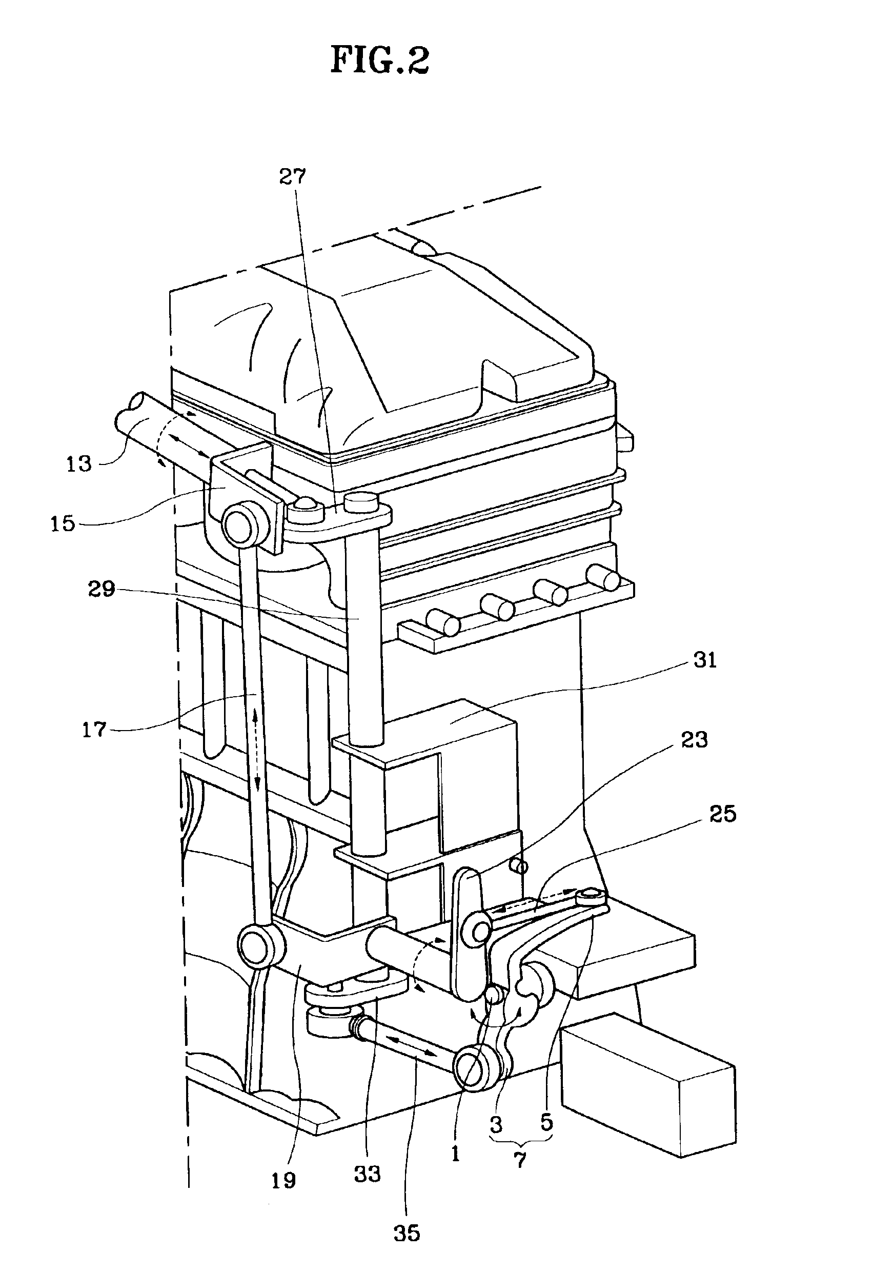
[0014]As shown in FIGS. 2, 3 and 4, a lever mechanism is coupled to a transmission. The lever mechanism is configured for selecting and shifting into a gear. The lever mechanism includes a shift lever 1 at the side of the transmission for performing a gear selection operation in response to a linear movement, and for performing a gear shifting operation in response to rotation. The lever mechanism also includes a manipulated lever 7 mounted at the shift lever 1 at the side of the transmission, including a rotating arm 3 and a linear movement arm 5.

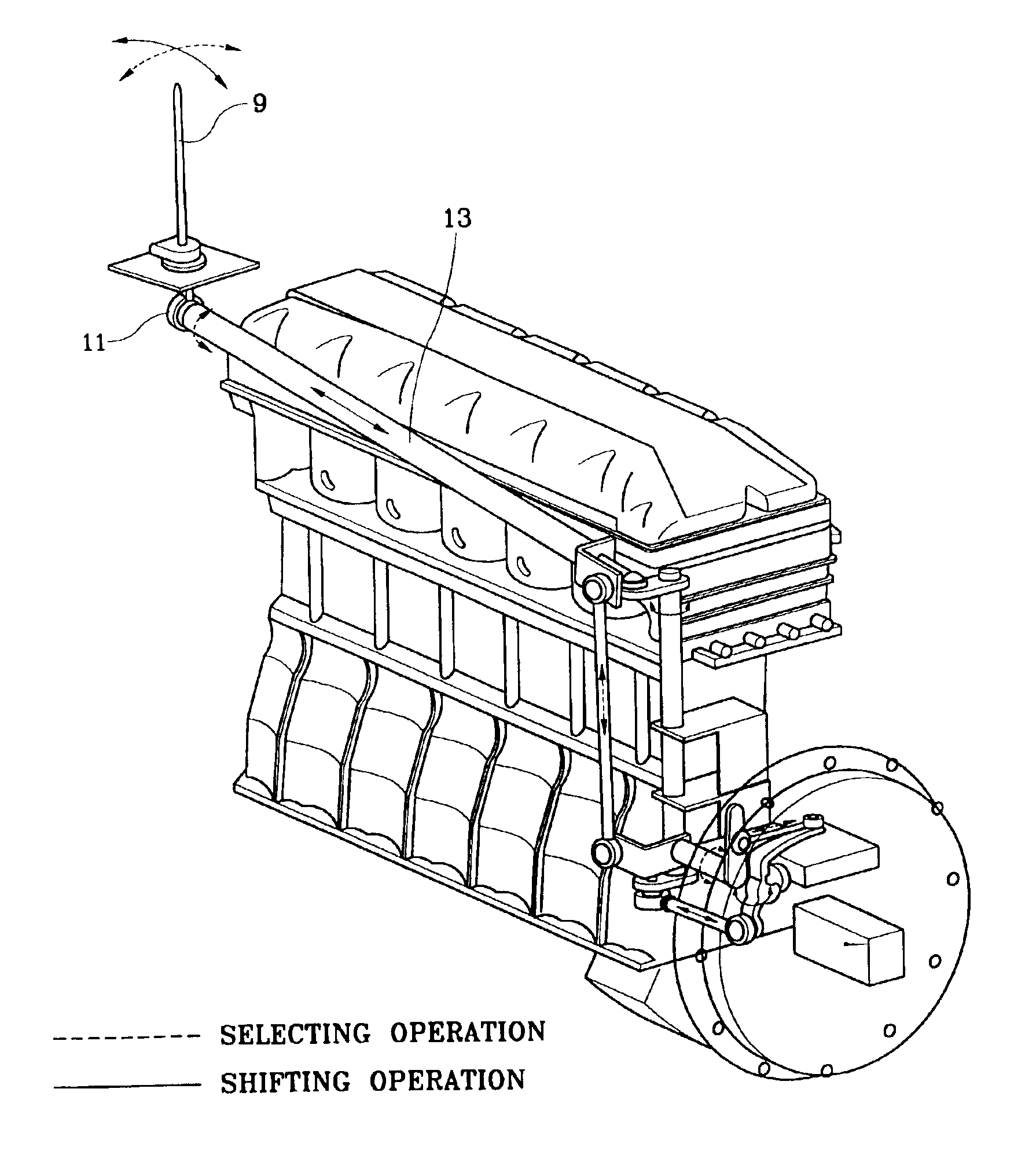
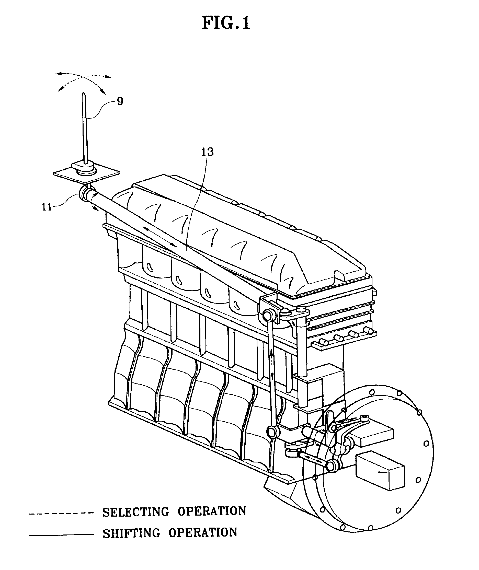
[0015]A shifting force from a shift lever 9 (FIG. 1) near the driver's seat is transmitted through a mechanical link system to the levers 1 and 7. The mechanical link system includes a first rod 13, a selecting line motion converter, a selecting link mechanism, a shifting rotation converter, and a shifting link mechanism.

[0016]The first rod 13 is coupled at one end thereof to a lower end of the shift lever 9 near the driver's seat (coupled...


PUM


Abstract

A manual transmission shifting device in which a shifting force is transmitted only by a first rod from a shift lever to a transmission and the shifting force transmitted to the first rod is supplied to the transmission via a simple mechanical link system, such that the number of components is reduced, thereby improving the efficiency of transmitting the shifting force to a transmission.

Description

FIELD OF THE INVENTION[0001]The present invention relates to a manual transmission shifting device, and more particularly, to a manual transmission shifting device for heavy-duty vehicles.BACKGROUND OF THE INVENTION[0002]When an operator (or driver) manipulates a shift lever in a manual transmission vehicle, shifting force is transmitted to a transmission gear box to shift a gear. In a small compact car, this shifting force is typically transmitted via a cable. However, in heavy-duty vehicles such as buses, trucks or the like, the shifting force is transmitted to the transmission via a plurality of link members. This is because the components to be shifted are large and heavy, and the distance covered by the shifting force is relatively far.[0003]Conventionally, in order to transmit a shifting force from a driver to the transmission, two separate forces, applied in two directions, are required. These forces are combined to shift the transmission into gear in multiple stages. In othe...

Claims


Application Information

Patent Timeline
IPC IPC(8): F16H59/04B60K20/04
CPCF16H59/042Y10T74/20018Y10T74/20159Y10T74/20165B60K20/04
Inventor RYU, SEUNG-DOON
Owner HYUNDAI MOTOR CO LTD
Why Eureka
Try Eureka