Vehicle lamp

a technology for lamps and vehicles, applied in fixed installations, lighting and heating apparatus, semiconductor devices for light sources, etc., can solve problems such as glare of reflectors, and achieve the effect of reducing the size of reflectors and being easy to control

Inactive Publication Date: 2005-10-04
KOITO MFG CO LTD
View PDF15 Cites 88 Cited by
  • Summary
  • Abstract
  • Description
  • Claims
  • Application Information

AI Technical Summary

Benefits of technology

[0015]Consequently, the light from the LED light source can be caused to be incident on the range extending even to the peripheral edge of the reflective surface, without increasing the depth of the reflector. Since the light from the LED light source is incident in the form of substantially paralle

Problems solved by technology

Consequently, there arise problems in that it is difficult to form the reflective surface so that, when the reflector is observed from the front side of the

Method used


Image

  • Vehicle lamp
  • Vehicle lamp
  • Vehicle lamp

Examples


Embodiment Construction

[0038]Hereinafter, an embodiment of the invention will be described with reference to the accompanying drawings.

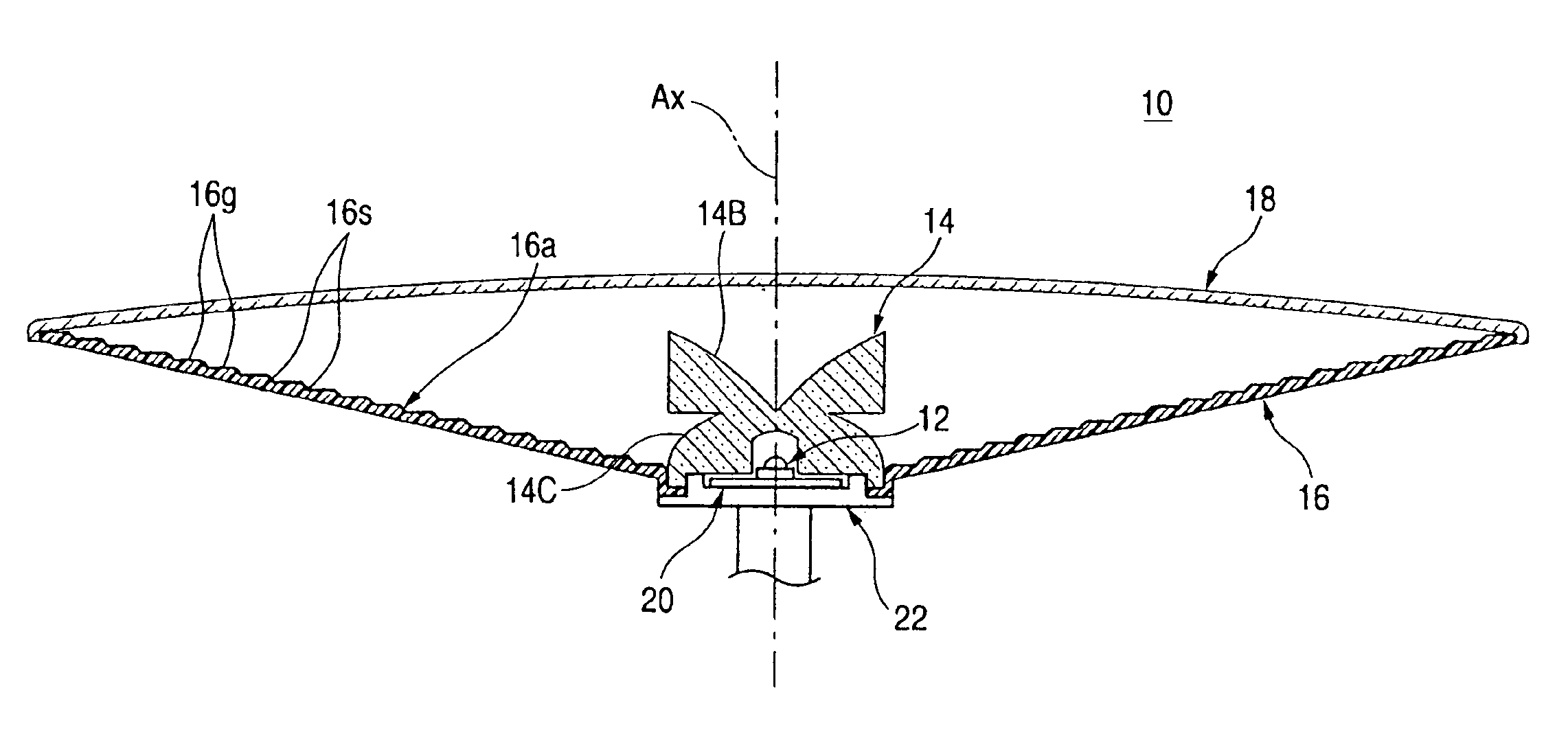
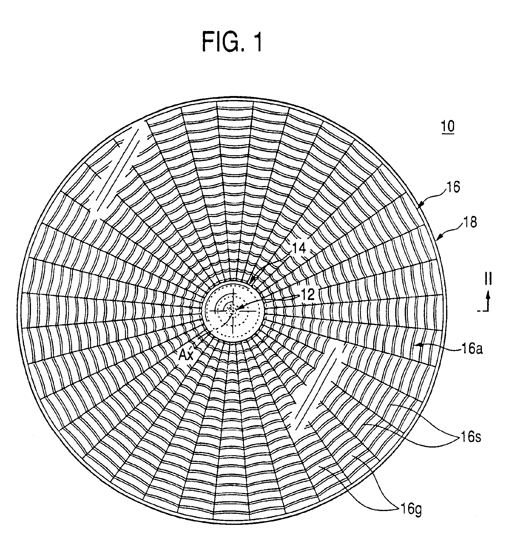
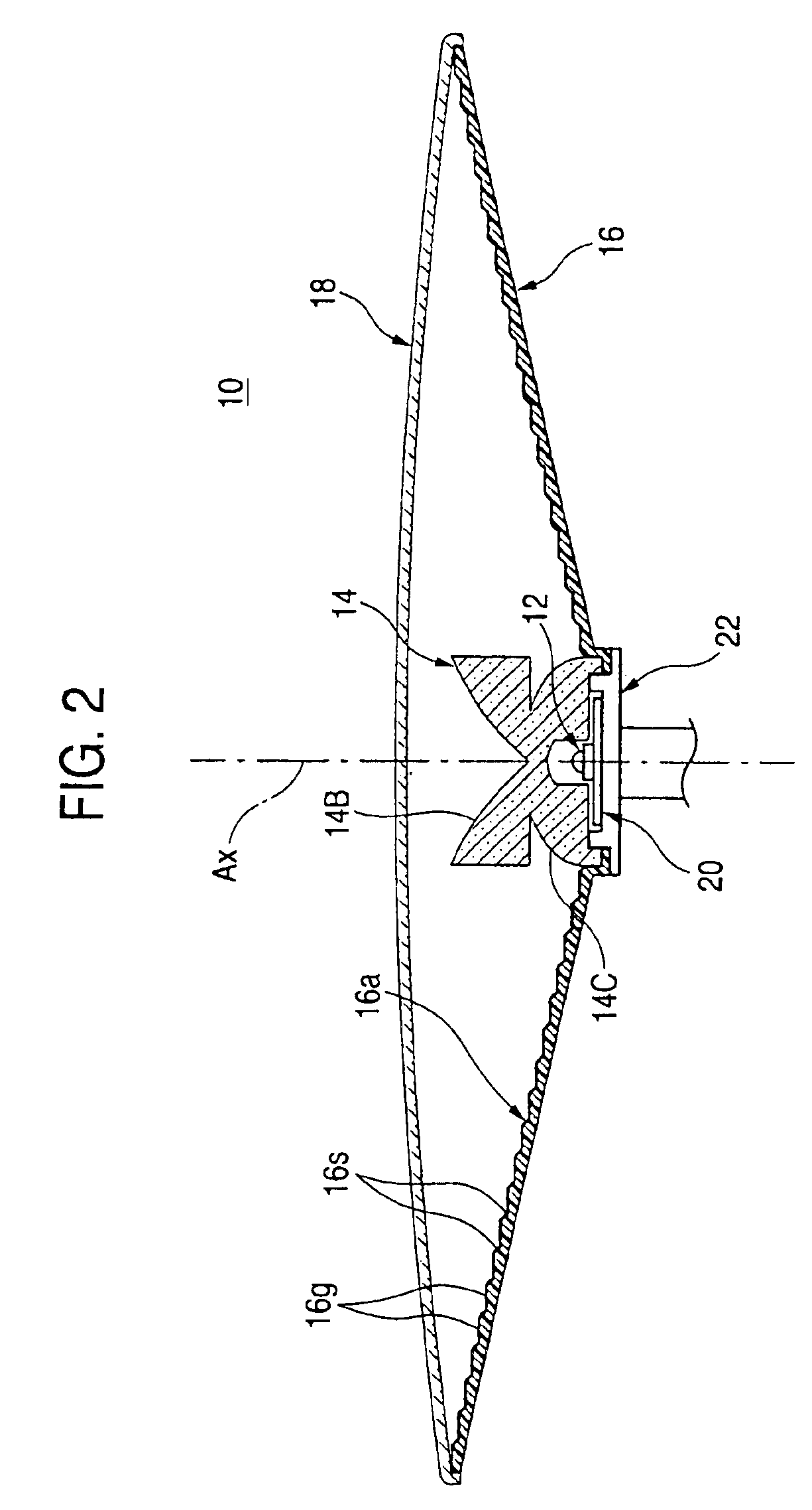
[0039]FIG. 1 is a front view showing a vehicle lamp of the embodiment, FIG. 2 is a section view taken along line II—II of FIG. 1, and FIG. 3 is a detail view of main portions of FIG. 2.

[0040]As shown in the figures, the vehicle lamp 10 of the embodiment is a tail lamp which is to be mounted on a rear end of a vehicle, and comprises an LED light source 12, a translucent member 14, a reflector 16, and a translucent cover 18.

[0041]The LED light source 12 is placed to be directed toward the front of the lamp (“rear side” of the vehicle, the same shall apply hereinafter) so that the optical axis Ax coincides with the center axis of the lamp which elongates in the longitudinal direction of the vehicle. The LED light source 12 consists of an LED main unit (LED chip) 12A, and a sealing resin 12B which covers the luminescence center O of the LED main unit 12A in a hemispherical man...


PUM


Abstract

Light from an LED light source, which is placed to be directed toward the front of a lamp, is incident on a translucent member, and the light that is transmitted through the translucent member is reflected by a reflector toward the front of the lamp. An internal reflection portion that internally reflects light which is incident on the translucent member at a small angle with respect to an optical axis of the LED light source, in a direction which is substantially perpendicular to the optical axis, and a refraction portion that refracts light which is incident at a large angle with respect to the optical axis, in a direction which is substantially perpendicular to the optical axis, are formed on the surface of the translucent member. The LED emitted light can be caused to be incident on a reflective surface of the reflector in the form of substantially parallel beams which are directed in a direction that is substantially perpendicular to the optical axis. The LED emitted light can be caused to be incident on the range extending even to the peripheral edge of the reflective surface, without increasing the depth of the reflector. The reflection due to the reflector can be easily controlled.

Description

BACKGROUND OF THE INVENTION[0001]1. Field of the Invention[0002]The present invention relates to a vehicle lamp comprising an LED (Light Emitting Diode) light source. More particularly, the present invention related to a vehicle lamp which comprises an LED light source in which a whole reflective surface of a reflector of the lamp can be seen glaring while the reflector size is reduced.[0003]2. Description of the Related Art[0004]Recently, vehicle lamps comprising an LED light source have been widely used. JP-UM-A-61-153201 discloses a vehicle lamp which is configured in the following manner. Light emitted from an LED light source, which is placed to be directed toward the front of the lamp, is incident on a translucent member. The light from the LED light source that is transmitted through the translucent member is reflected toward the front of the lamp by a reflector which is formed integrally with the translucent member.[0005]When a lamp is configured as described above, the ligh...

Claims


Application Information

Patent Timeline
IPC IPC(8): F21V7/00F21S8/10F21V13/00F21V13/04F21V7/04F21W101/14F21Y101/02H01L33/54H01L33/60
CPCF21S48/215F21S48/2243F21S48/225F21S48/2262F21S48/2287F21S48/236F21V7/0091F21S48/2268F21Y2101/02F21S48/24F21Y2115/10F21S43/14F21S43/239F21S43/241F21S43/243F21S43/245F21S43/247F21S43/315F21S43/40F21S43/30F21Y2105/10F21W2103/00
Inventor AMANO, YASUYUKIKOIZUMI, HIROYA
Owner KOITO MFG CO LTD
Why Eureka
Try Eureka