
Attachment plate for directly mating circuit boards

a technology for attaching plates and printed circuit boards, which is applied in the direction of printed circuit board receptacles, fixed connections, coupling devices, etc., and can solve problems such as pin bend, pin damage, and pin bending

Inactive Publication Date: 2005-10-04
HEWLETT PACKARD DEV CO LP
View PDF8 Cites 63 Cited by
  • Summary
  • Abstract
  • Description
  • Claims
  • Application Information

AI Technical Summary

Benefits of technology

The invention is about a way to connect two circuit boards together without applying any force to the first circuit board. The apparatus includes an attachment plate, extension arms, a pressure platform, and attachment elements to secure the plate to the second circuit board. The method involves suspending the first circuit board over the second circuit board and applying a mating force to the rear side of the first circuit board to connect the two integrated connectors. The technical effect is that this invention allows for a more gentle and secure connection between circuit boards.

Problems solved by technology

Problems can arise when directly mating circuit boards such as the noted daughtercard and motherboard.
If the force applied to the connectors during mating is not parallel to the pins and sockets of the connectors; for example, if the circuit boards are not maintained in parallel planes or laterally translate during mating, damage to the connector pins and sockets can easily result.
Under some circumstances, this can result in the bending of pins, incomplete electrical contact between some pins and their corresponding sockets, or other types of connection failures.

Method used


Image

  • Attachment plate for directly mating circuit boards
  • Attachment plate for directly mating circuit boards
  • Attachment plate for directly mating circuit boards

Examples


Embodiment Construction

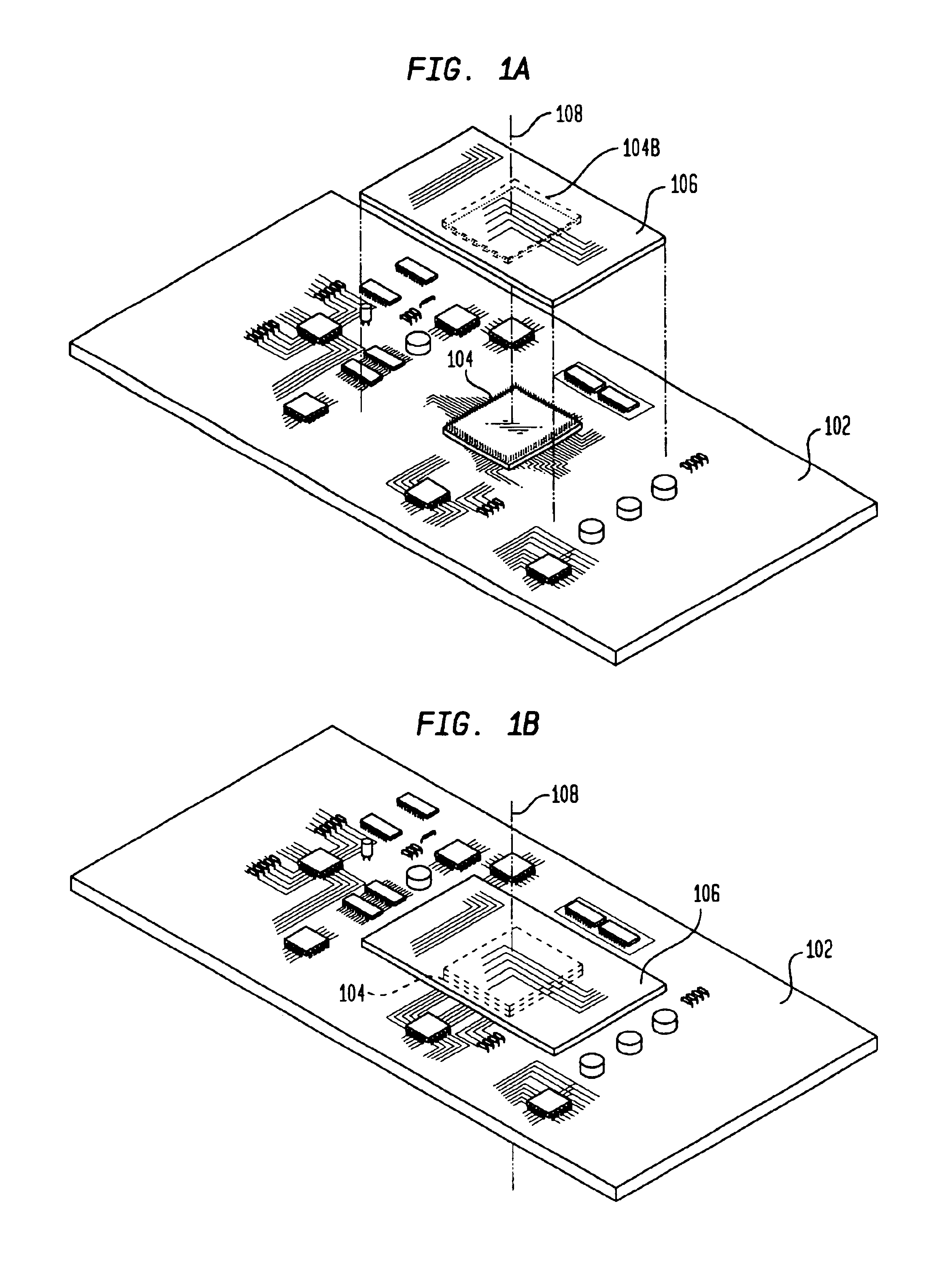
[0016]The present invention is directed to an apparatus for facilitating the direct electrical connection between two printed circuit boards each having an integrated electrical connector. FIGS. 1A and 1B are perspective views of two printed circuit boards, a motherboard 102 and a daughtercard 106. Motherboard 102 has an integrated electrical connector 104A. Similarly, daughtercard 106 has an integrated connector or socket 104B. Connectors 104A and 104B are corresponding halves of a conventional connector 104 such as ZIP socket, zero force insertion socket, and the like.

[0017]When daughtercard 106 and motherboard 102 are mated, they are brought together along a mating axis 108 parallel with the longitudinal axis of the pins and receptacles of connector 104, as shown in FIG. 1B. A force substantially parallel with mating axis 108 (referred to as a mating axis force) is then applied to daughtercard 106 to urge the daughtercard toward motherboard 102. Such mating axis forces cause the ...


PUM


Abstract

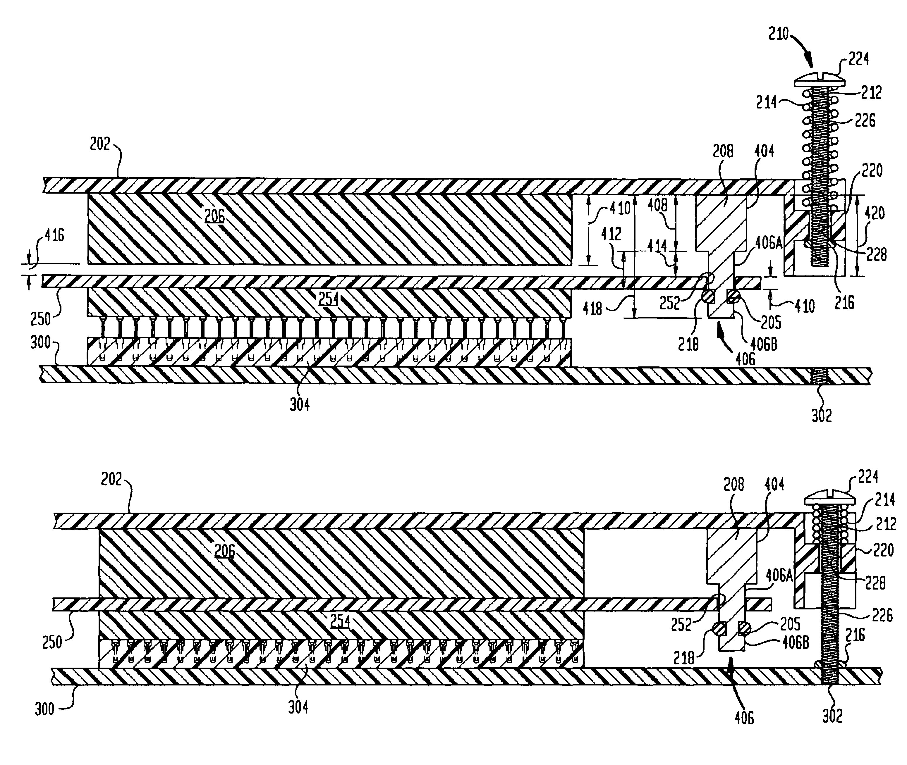
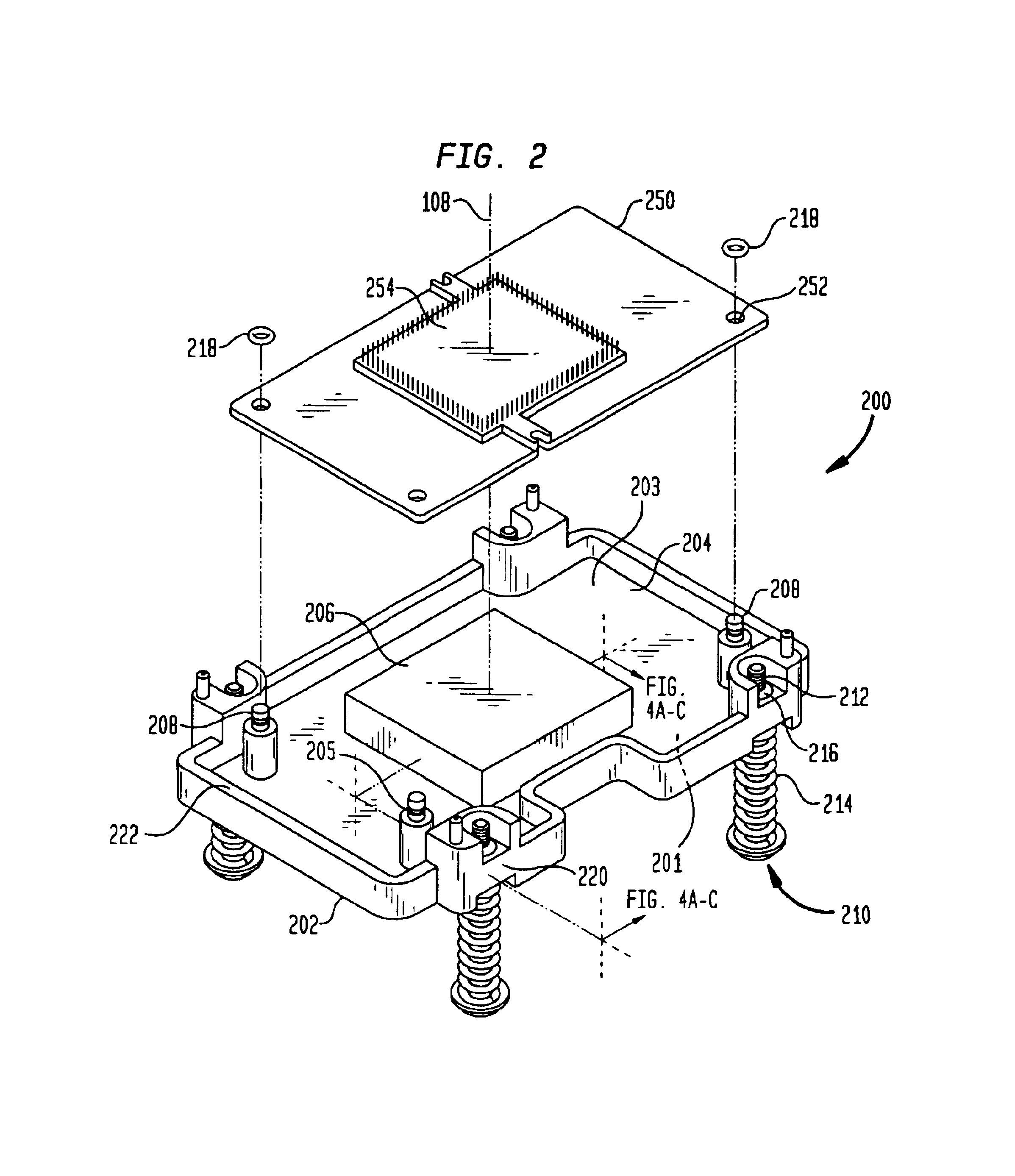
An apparatus for adjoining along a mating axis a first and second circuit board to directly mate a first integrated connector of the first board with a second integrated connector of the second board is disclosed. The apparatus comprises an attachment plate to be supported in a substantially horizontal plane; a plurality of extension arms extending downward from the plate to suspendingly restrain the first board away from the plate except to permit the first board to translate along the mating axis toward the plate; an pressure platform extending downward from the plate to apply to the first board a mating-axis force collocated with the first connector; and a plurality of attachment elements to secure the plate to the second circuit board without applying forces to the first circuit board. Forces applied to the plate are transferred to the first board through only the pressure platform.

Description

BACKGROUND[0001]1. Field of the Invention[0002]The present invention relates generally to printed circuit boards and, more particularly, to a daughtercard attachment plate for directly mating printed circuit boards.[0003]2. Related Art[0004]Computer systems have one or more printed circuit boards on which various digital and / or analog components are mounted. The principal printed circuit board in a computer system is generally referred to as a motherboard. In personal computers, the motherboard is often called the system board or mainboard. Typically, the motherboard holds many of the digital components integral to the functioning of a computer system such as the CPU, memory and basic controllers. In many instances, additional circuit boards can be attached to the motherboard to provide additional functionality. Such additional circuit boards include expansion boards and daughtercards (sometimes referred to as daughterboards). Expansion boards are circuit boards that plug into the c...

Claims


Application Information

Patent Timeline
Patent Type & Authority Patents(United States)
IPC IPC(8): H05K3/30H05K7/14H01R13/621H05K1/14H01R12/16
CPCH01R9/096H05K3/301H05K7/1431H01R13/6215H05K1/141H01R12/52H01R12/00H01R13/631
Inventor SANDOVAL, ALISAMEYER, GREGORY S.
Owner HEWLETT PACKARD DEV CO LP
Learn More