
Method and apparatus for the identification and characterization of regions of altered stiffness

a technology of altered stiffness and ultrasonic sound, which is applied in the field of ultrasonic methods and apparatus for the identification and characterization of regions of altered stiffness, can solve the problems of remote palpation not being implemented in a form feasible for actual clinical diagnosis, multiple pushing cycles at a single location, and different transmit and detection systems. achieve the effect of remote palpation, facilitate real-time, and facilitate implementation

Inactive Publication Date: 2005-10-04
DUKE UNIV
View PDF9 Cites 86 Cited by
  • Summary
  • Abstract
  • Description
  • Claims
  • Application Information

AI Technical Summary

Benefits of technology

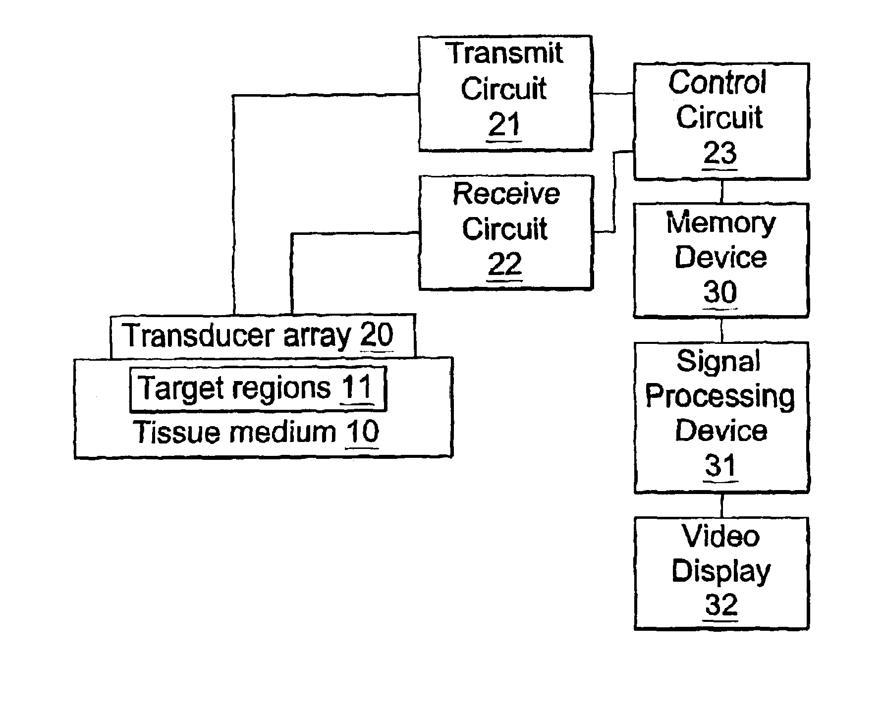
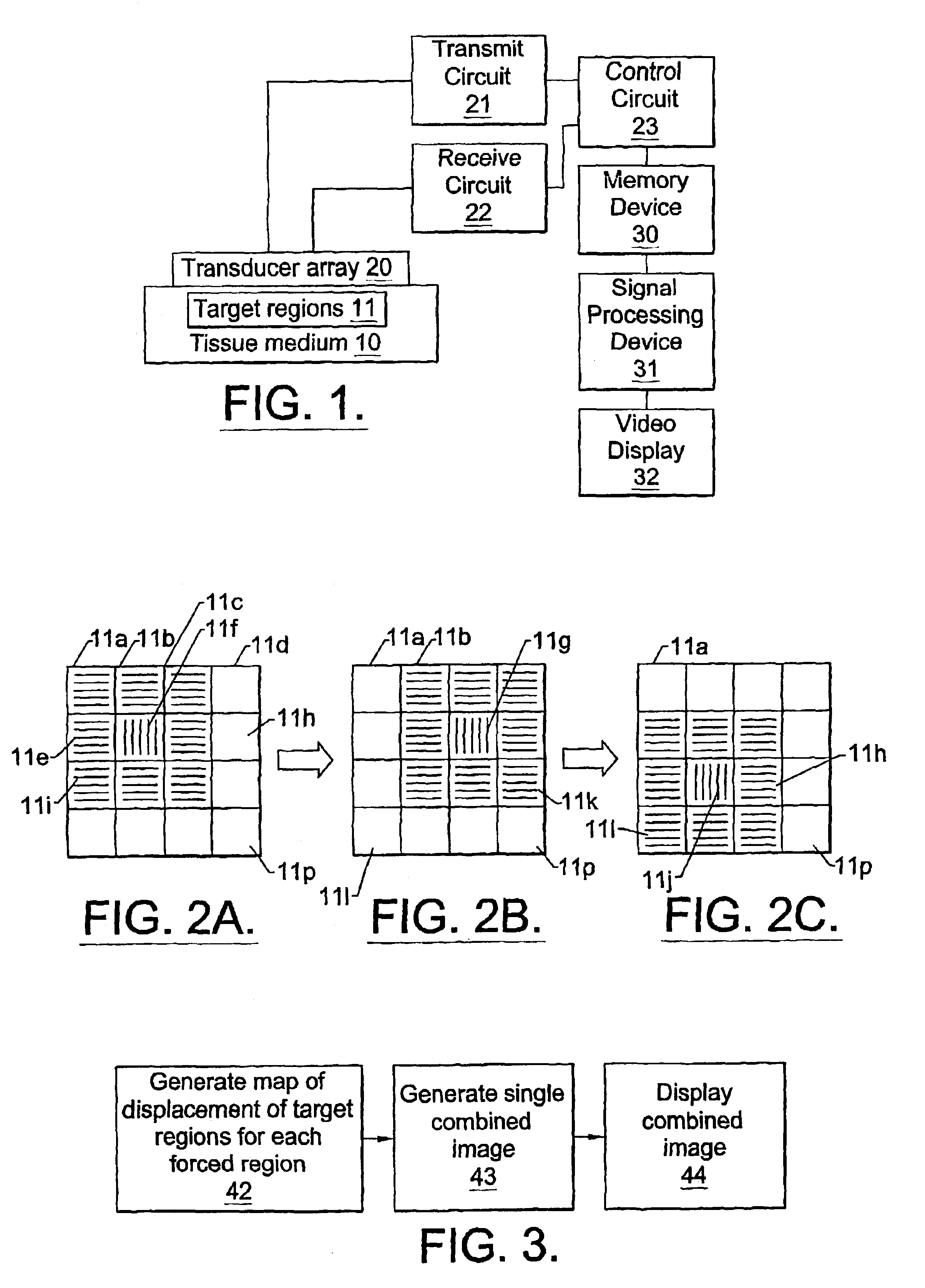
[0008]The present invention is based upon the finding that an improved implementation of remote palpation in breast imaging can involve the use of multiple applications of radiation force in rapid succession throughout a two-dimensional plane in the target tissue, and the combination of the small, two-dimensional displacement maps from each force location into a single, larger remote palpation image. The use of multiple forcing locations may present a significant improvement in the remote palpation method, in that it may facilitate real-time, implementation of the method, which can allow more thorough interrogation of a suspicious region of tissue, as well as correlation and superposition of remote palpation images and conventional B-mode images. It may also reduce or even obviate the need for bulky, complex external fixtures during implementation of the method.

Problems solved by technology

A disadvantage of such am approach is that different transmit and detection systems may be required, and multiple pushing cycles at a single location may be required.
Remote palpation has not yet been implemented in a form feasible for actual clinical diagnosis.

Method used


Image

  • Method and apparatus for the identification and characterization of regions of altered stiffness
  • Method and apparatus for the identification and characterization of regions of altered stiffness
  • Method and apparatus for the identification and characterization of regions of altered stiffness

Examples


Embodiment Construction

[0017]While the present invention may be used to detect regions of varying stiffness (i.e., increased or decreased elastic modulus) in any type of medium, the medium is in a preferred embodiment a biological tissue such as breast tissue in a living subject, where the regions of varying stiffness to be detected are tumors.

[0018]The invention may be carried out on human subjects for diagnostic or prognostic purposes, and may be carried out on animal subjects such as dogs and cats for veterinary purposes.

[0019]Circuits and devices described herein may be implemented as general or special purpose hardware devices, as software running on or programmed into general or special purpose hardware devices, or as combinations thereof.

[0020]Numerous variations and implementations of the instant invention will be apparent to those skilled in the art. Ultrasound apparatus is known, and is described in, for example, U.S. Pat. No. 5,487,387 to Trahey et al.; U.S. Pat. No. 5,810,731 to Sarvazyan and ...


PUM


Abstract

A remote palpation technique in breast imaging involves the use of multiple applications of radiation force in rapid succession throughout a two-dimensional plane in the target tissue medium (10), and combination of the small, two-dimensional displacement maps from each force location into a single, larger remote palpation image (block 43). Apparatus for carrying out the foregoing method is also disclosed.

Description

RELATED APPLICATIONS[0001]This application claims priority from International PCT Application No. US01 / 11051, filed Apr. 5, 2001 and is a continuation of U.S. application Ser. No. 09 / 663,271, filed Sep. 18, 2000, now U.S. Pat. No, 6,371,912, which claimed the benefit of U.S. Provisional Application Ser. No. 60 / 194,746, filed Apr. 5, 2000, the disclosures of which are incorporated by reference herein in their entireties.GOVERNMENT SUPPORT[0002]This invention was made with Government support under grant number DAMD17-98-1-8068 from the Department of Defense. The Government has certain rights to this invention.FIELD OF THE INVENTION[0003]The present invention concerns ultrasound methods and apparatus for the identification and characterization of regions of altered stiffness in a target media.BACKGROUND OF THE INVENTION[0004]The early detection of breast cancer has been shown to significantly improve patient survival. Present methods of breast cancer detection include screening mammogr...

Claims


Application Information

Patent Timeline
Patent Type & Authority Patents(United States)
IPC IPC(8): A61B5/103A61B8/08
CPCA61B5/0053A61B5/02007A61B5/4312A61B5/489A61B8/08A61B8/0825A61B8/485G01S7/52042G01S7/52022A61B5/4519A61B8/0833G01S15/8993G01S15/8915
Inventor TRAHEY, GREGG E.NIGHTINGALE, KATHRYN R.NIGHTINGALE, ROGER W.PALMERI, MARK
Owner DUKE UNIV
Learn More