
Concealed wireless sensor with external antenna

a wireless sensor and antenna technology, applied in the field of security systems, can solve the problems of affecting the decor of the premises, affecting the service life of the device, and the device is too large to be recessed within the door or window, so as to achieve the effect of improving the transmission and/or reception, facilitating mounting, and facilitating the installation

Active Publication Date: 2005-10-04
ADEMCO INC
View PDF10 Cites 37 Cited by
  • Summary
  • Abstract
  • Description
  • Claims
  • Application Information

AI Technical Summary

Benefits of technology

The present invention is a wireless security device that can be embedded within a door, window, or frame, with only the antenna mounted on the surface of the door or window jamb. The device has a housing with a security sensor circuit, RF transmitter, and power source. A flat surface mountable strip is located outside the housing and has an antenna that emits electromagnetic energy corresponding to the RF signal from the transmitter. The strip is either embedded within the housing or physically separate from it, and is thin enough to not interfere with the operation of the door or window. The surface mountable strip is paintable and blends in with the decor of the premises. The technical effects of this invention are easy mounting, improved transmission and reception, and a more predictable antenna pattern.

Problems solved by technology

Current door and window motion sensors are visible and thus detract from the decor of the premises.
Embedding such devices typically will provide an inferior product since the RF transmissions are attenuated when the antenna is placed close to a printed circuit board and / or battery.
Mounting the antenna on the PC board often causes the device to be too large to recess within a door or window.

Method used


Image

  • Concealed wireless sensor with external antenna
  • Concealed wireless sensor with external antenna
  • Concealed wireless sensor with external antenna

Examples


Embodiment Construction

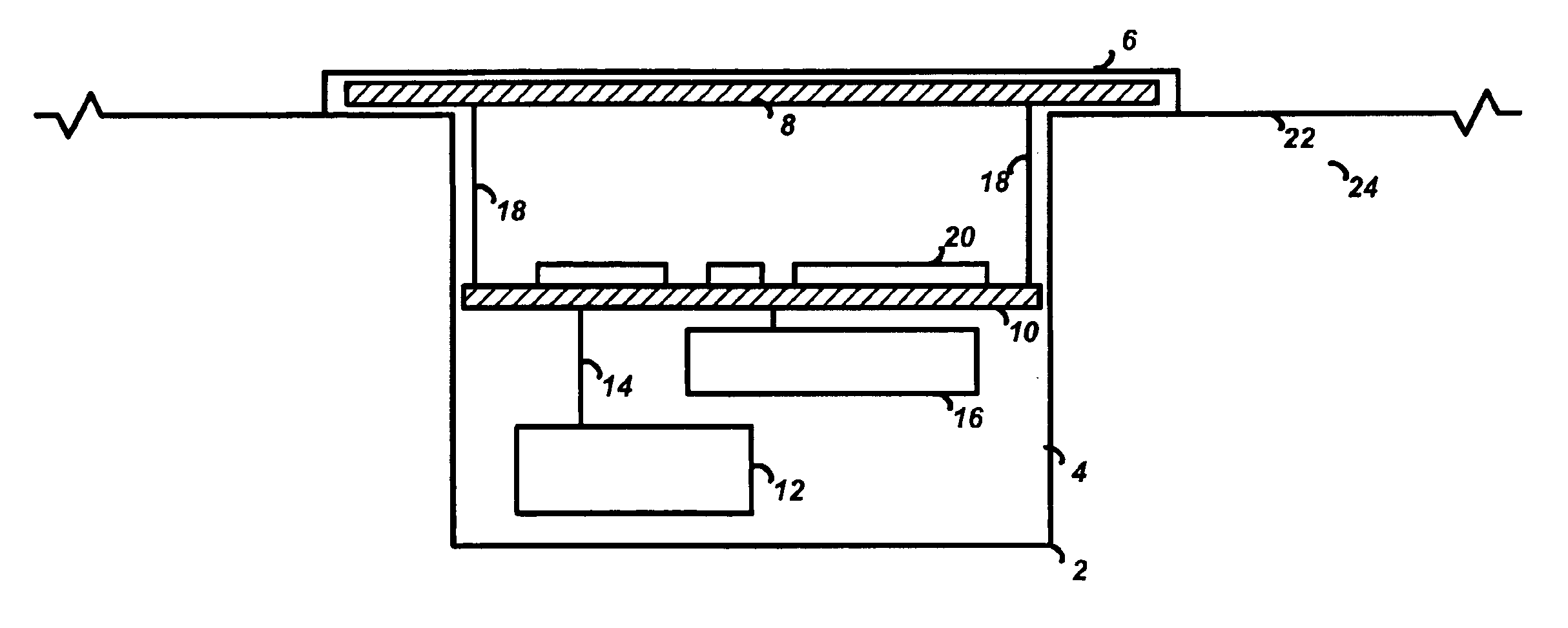
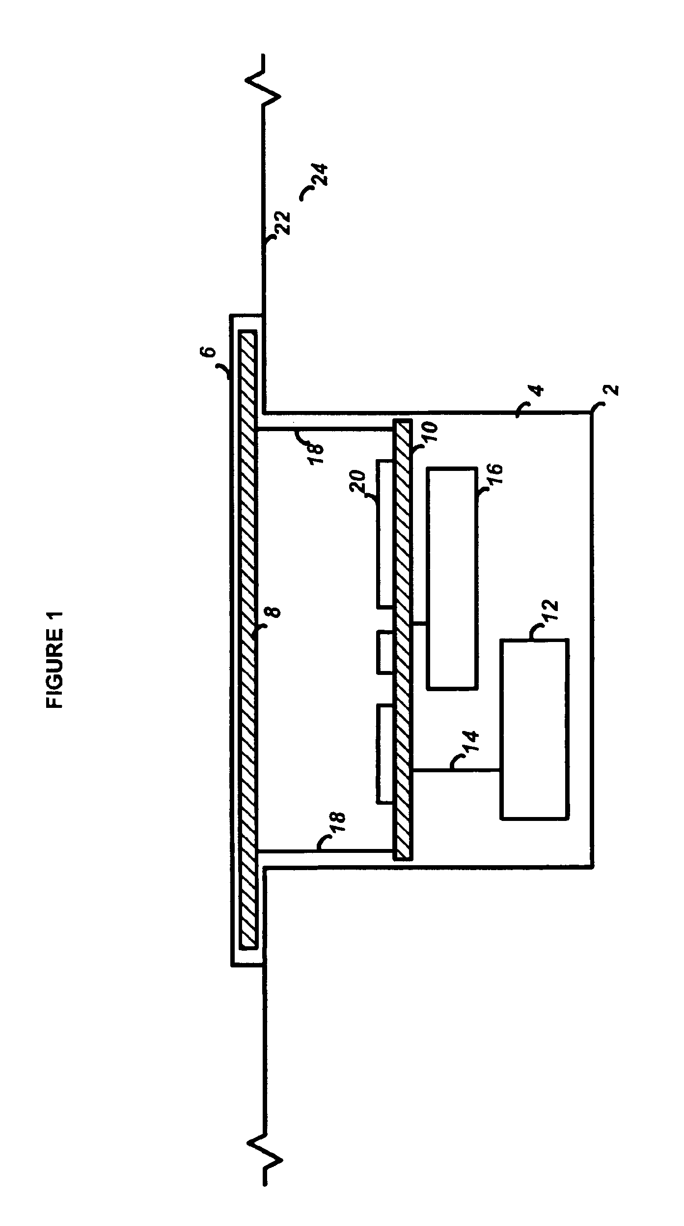
[0011]The preferred embodiment of the present invention will now be described with respect to FIG. 1. Shown is a wireless security device 2 which has a cylindrical housing 4 and a surface mountable strip in the form of a round, substantially flat top portion 6. The housing is preferably cylindrical so that an installer can bore a hole within a structure 24 such as a window or door, and then easily insert the cylindrical housing into the hole. The housing may also be in other shapes, such as a rectangular prism, as desired by the designer. By making the top portion 6 longer in length than the housing, the top portion will rest easily against the surface 22 of the structure 24. The dimensions of the housing 4 and the hole may be configured so that the housing 4 will press fit snugly within the hole, or an adhesive may be used to provide for secure mounting. The top portion 6 is relatively thin, preferably on the order of approximately 0.050″ thick, so that it lays substantially flat a...


PUM


Abstract

A wireless security device, such as a door or window motion sensor, that can be mounted almost entirely within a recess of a door, window or frame, with only the antenna mounted on the surface of the door or window jamb. The wireless security device has a housing suitable for being embedded within a structure such as a door, window or frame. In the housing are a security sensor circuit adapted to generate an alarm signal when activated, a radio frequency (RF) transmitter connected to the security sensor circuit for transmitting an RF signal when the alarm signal is generated, and a power source (such as a battery, piezoelectric element, solar cell or fuel cell) for supplying operating power to the security sensor circuit and the RF transmitter. A substantially flat surface mountable strip is located in proximity to the housing and is suitable for being mounted outside (i.e. along the surface of the structure). The surface mountable strip has an antenna that is coupled to the RF transmitter for emitting electromagnetic energy corresponding to the RF signal from the transmitter. In addition, the embedded antenna provides a predictable transmission pattern resulting in increased range and reliability.

Description

BACKGROUND OF THE INVENTION[0001]The present invention relates to security systems, and in particular to a wireless security device that may be embedded within a recess in a door or window with an externally located antenna for superior signal transmission performance.[0002]Current door and window motion sensors are visible and thus detract from the decor of the premises. Embedding such devices typically will provide an inferior product since the RF transmissions are attenuated when the antenna is placed close to a printed circuit board and / or battery. Mounting the antenna on the PC board often causes the device to be too large to recess within a door or window.SUMMARY OF THE INVENTION[0003]The present invention is a wireless security device, such as a door or window motion sensor, that can be mounted almost entirely within a recess of a door, window or frame, with only the antenna mounted on the surface of the door or window jamb. The wireless security device has a housing suitable...

Claims


Application Information

Patent Timeline
Patent Type & Authority Patents(United States)
IPC IPC(8): G08B21/00G08B13/08G08B13/02
CPCG08B13/08
Inventor KOVACH, JOHN MESKILDSEN, KENNETH G
Owner ADEMCO INC
Learn More