Face portion detecting apparatus

a technology of detecting apparatus and face portion, which is applied in the field of face portion detecting apparatus, can solve the problems of erroneous detection of reflection image 142/b> from the surface of the spectacle lens, inability to correctly extract the eye portion, and certain probability, so as to avoid cumbersome operation of mounting a specific apparatus.

Inactive Publication Date: 2005-10-04
MITSUBISHI ELECTRIC CORP
View PDF12 Cites 34 Cited by
  • Summary
  • Abstract
  • Description
  • Claims
  • Application Information

AI Technical Summary

Benefits of technology

[0017]The present invention has been made to solve the above-explained problems, and therefore, has an object to provide such a face portion detecting apparatus capable of firmly detecting a desired face portion even when a human being wears such an article having a luster reflection surface as spectacles or a helmet, while cumbersome operation of mounting a specific apparatus can be avoided.
[0024]In the face portion detecting apparatus according to the present invention, at least a portion of the one illumination means is arranged within a range separated from the optical axis of the photographing means by a constant distance, and the illumination means owns a predetermined shape; the illumination lighting control means turns ON the illumination means while one image is photographed; and the face portion detecting means detects as the retina reflection image, such a reflection image which is present within constant region among the images acquired by the photographing means, and the luminance level of which is higher than, or equal to a predetermined value, and furthermore, removes such a reflection image having a shape identical to the predetermined shape of the illumination means as the reflection image of the article having the luster reflection surface.
[0025]In the face portion detecting apparatus according to the present invention, at least one of the plurality of illumination means is arranged within a range separated from an optical axis of the photographing means by a constant distance, and the plurality of illumination means are arranged in such a manner that the plural illumination means constitute a predetermined shape; the illumination lighting control means turns ON the plurality of illumination means while one image is photographed; and the face portion detecting means detects as the retina reflection image, such a reflection image which is present within a constant region among the images acquired by the photographing means, and the luminance level of which is higher than, or equal to a predetermined value, and furthermore, removes such a reflection image having a shape identical to the predetermined shape of the plurality of illumination means as the reflection image of the article having the luster reflection surface.

Problems solved by technology

In the above-explained detecting apparatus disclosed in Japanese Patent Laid-opens No. 06-270711 and No. 09-081756, however, in such a case that the human being wears spectacles, there are such possibilities that the eye portion cannot be correctly extracted due to the adverse influences caused by the reflection image, which occurs on the luster reflection surfaces of the spectacles.
As a result, there is a certain probability that the reflection image 142 reflected from the surface of the spectacle lens is erroneously detected as the retina reflection image.
However, this suppression effect cannot be achieved, depending upon the angles of the head portion.
Furthermore, in the detecting apparatus disclosed in Japanese Patent Laid-open No. 10-216234, since the human being must wear the specific spectacles, the human being feels cumbersome, which is a problem.

Method used


Image

  • Face portion detecting apparatus
  • Face portion detecting apparatus
  • Face portion detecting apparatus

Examples


embodiment 1

[0048

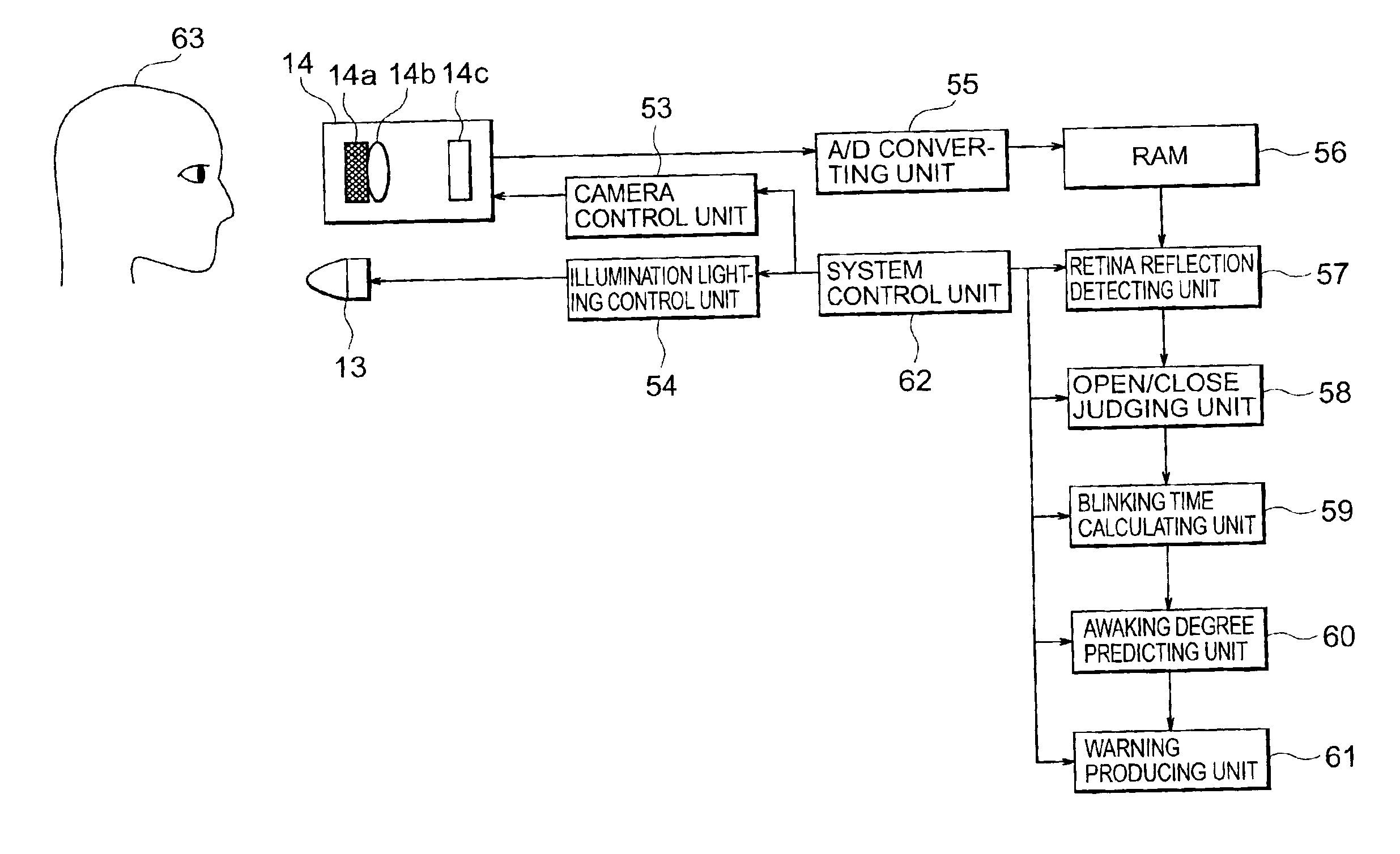
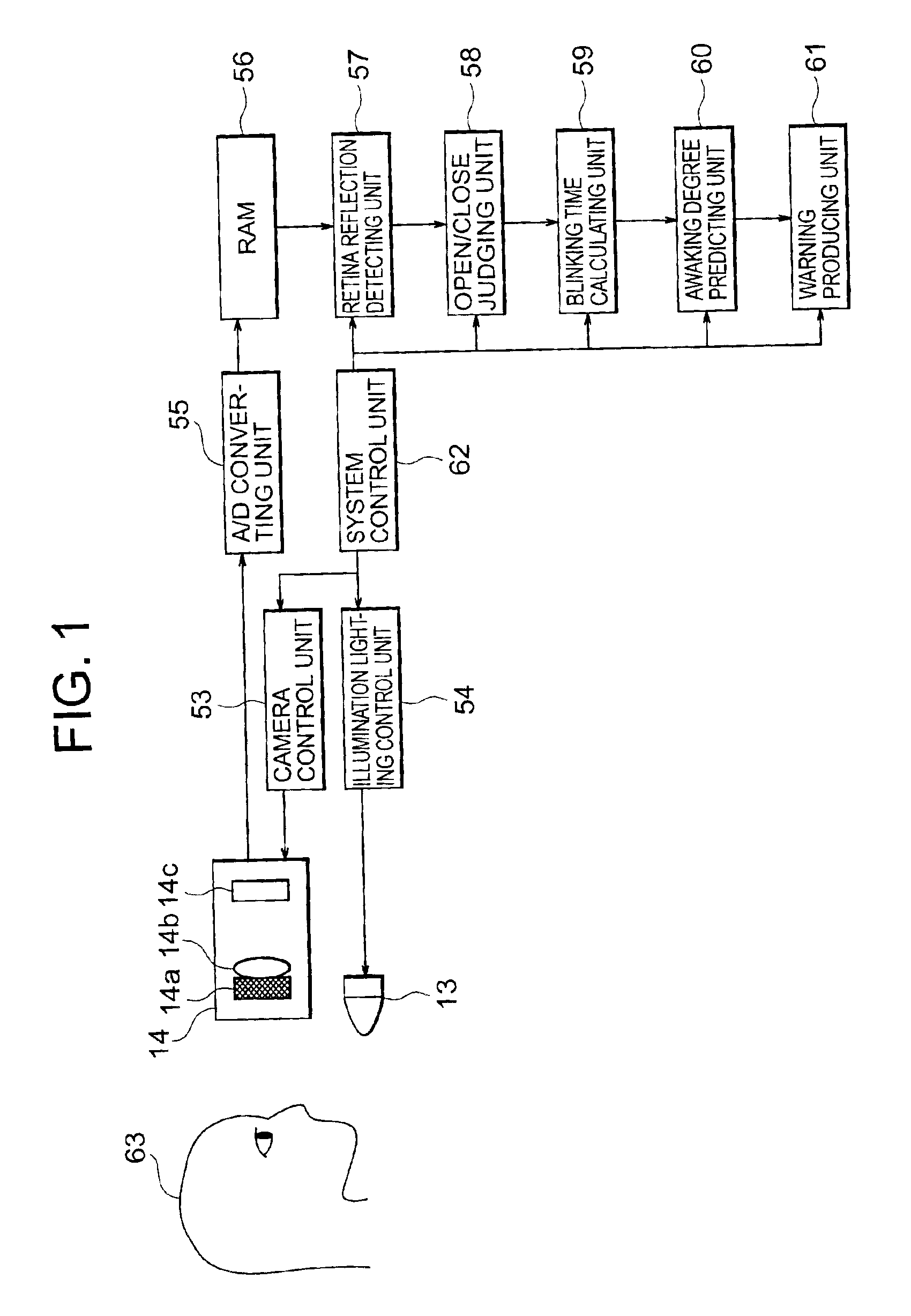
[0049]First, a face portion detecting apparatus according to an embodiment 1 of the present invention will now be explained with reference to drawings. FIG. 1 schematically shows an overall arrangement of a face portion detecting apparatus according to the embodiment 1 of the present invention. It should be understood that the same reference numerals shown in the respective drawings denote the same or similar structural elements in the present invention.

[0050]In FIG. 1, reference numeral 14 shows a camera (photographing means). The camera 14 is composed of an optical filter 14a, a lens 14b, and a photographing element 14c. Also, reference numeral 13 shows a light source of an illumination (illumination means). Both the camera (photographing means) 14 and the illumination light source (illumination means) 13 are controlled by a camera control unit (photographing control means) 53 and an illumination lighting control unit (illumination lighting control means) 54, respectively. As...

embodiment 2

[0074

[0075]Referring now to drawings, a description will be made of a face portion detecting apparatus according to an embodiment 2 of the present invention. It should be understood that an overall arrangement of this face portion detecting apparatus according to the embodiment 2 is similar to that of the face portion detecting apparatus according to the above-explained embodiment 1.

[0076]FIG. 7 and FIG. 8 illustratively show contents of the second embodiment 2 of the present invention. In this embodiment 2, two or more illumination light sources 13 are arranged on a straight line as illustrated in FIG. 7.

[0077]In FIG. 8, reference numeral 17 indicates a reflection image reflected on the surface of the spectacle lens 12 photographed by the camera 14.

[0078]In the case of FIG. 7, while a single image is photographed by the camera 14, a plurality of these illumination light sources 13 are continuously turned ON in either a sequential manner or a random manner in synchronism with the ph...

embodiment 3

[0083

[0084]Referring now to drawings, a description will be made of a face portion detecting apparatus according to an embodiment 3 of the present invention. It should be understood that an overall arrangement of this face portion detecting apparatus according to the embodiment 3 is similar to that of the face portion detecting apparatus according to the above-explained embodiment 1.

[0085]The illumination light sources 13 are arranged in the straight line form in the above-described embodiment 2, whereas a plurality of light sources 13 are arranged in a coaxial form with respect to the optical axis of the camera 14 in this embodiment 3. Referring now to FIG. 9 and FIG. 10, this face portion detecting apparatus of the embodiment 3 will be described.

[0086]FIG. 9 is a diagram for illustratively indicating a plurality of illumination light sources 13 and a camera 14, as viewed from a car driver. In FIG. 9, a plurality of illumination light sources 13 are arranged in a coaxial form with ...


PUM


Abstract

In a face portion detecting apparatus, an image of an eye portion of a car driver can be properly extracted without adverse influences caused by a reflection image reflected from a luster reflection surface of spectacles worn by the car driver. The face portion detecting apparatus is arranged by a light source of an illumination for illuminating a face portion of a human being from different directions from each other; a camera for photographing the face portion which is illuminated by the light source; an illumination lighting control unit for controlling turn-ON operation of the light source; a camera control unit for controlling the camera in synchronism with the turn-ON operation of the illumination light source; and a retina reflection detecting unit for removing a reflection image of an article having a luster reflection surface by employing at least one image which is acquired by the camera in synchronism with the turn-ON operation of the illumination light source, whereby only a determined face portion is extracted.

Description

[0001]This application is based on Application No. 2001-162079, filed in Japan on May 30, 2001, the contents of which are hereby incorporated by reference.BACKGROUND OF THE INVENTION[0002]1. Field of the Invention[0003]The present invention is related to a face portion detecting apparatus in which a human face portion is irradiated by light and a desirable face portion is detected while suppressing an adverse influence made by a reflection image caused by an article having a luster reflection surface such as spectacles (glasses).[0004]2. Description of the Related Art[0005]Conventionally, various methods for detecting eye portions by using reflection images produced by irradiating near infrared rays have been widely utilized. For instance, Japanese Patent Laid-open No. 06-270711 discloses a method operated in such a manner that while the near infrared rays are irradiated to the human eyeball portion, the pupil region of the eyeball portion is detected, and then blinking actions are ...

Claims


Application Information

Patent Timeline
Patent Type & Authority Patents(United States)
IPC IPC(8): G06K9/00G06K9/20A61B3/14B60K28/06G06T1/00G06V10/141
CPCG06K9/00255G06K9/00604G06K9/2027G06V40/166G06V40/19G06V10/141
Inventor ISHIKURA, HISASHI
Owner MITSUBISHI ELECTRIC CORP
Why Eureka
Try Eureka