Image forming apparatus adopting image bearing member cleaner-less system

Inactive Publication Date: 2005-10-04
CANON KK
View PDF11 Cites 32 Cited by
  • Summary
  • Abstract
  • Description
  • Claims
  • Application Information

AI Technical Summary

Benefits of technology

[0010]An object of the present invention is to prevent an occurrence of toner adhesion to a non-image portion in an image area in a cleaner-less type image forming apparatus including not only a

Problems solved by technology

Further, in the image forming apparatus of the type wherein the toner image formed on the image bearing member is transferred onto a recording material or the like, the toner remaining on the image bearing member is recovered by the cleaner, thus resulting in waste toner.
However, this is not desirable environmentally.
However, in the case where such a voltage superposed with the AC voltage is applied, the toner is charge-removed by the AC voltage to reduce the electrostatic repulsive force, thus causing the toner adhesion to the contact charging member.
However, in the case where the bias voltage applied to the charg

Method used


Image

  • Image forming apparatus adopting image bearing member cleaner-less system
  • Image forming apparatus adopting image bearing member cleaner-less system
  • Image forming apparatus adopting image bearing member cleaner-less system

Examples


second embodiment

[0119]Next, the present invention will be described.

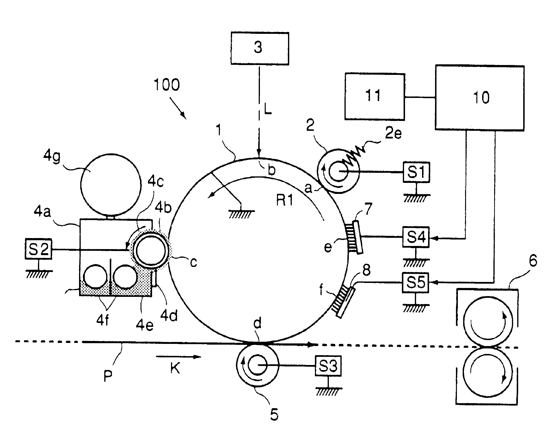
[0120]In this embodiment, the general structure of an image forming apparatus (laser beam printer) is similar to that of the image forming apparatus used in Embodiment 1. Accordingly, respective members having the same function and structure identical to those of the printer 100 used in Embodiment 1 are represented by identical reference numerals or symbols and detailed explanations therefor are omitted.

embodiment 1

[0121]In Embodiment 1, the control such that the control values of DC voltages to be applied to the toner charging means 7 and the electrostatic latent image erase means 8 were continuously increased linearly in accordance with the integrated time values of voltage application to the toner charging means 7 and the electrostatic latent image erase means 8 as the amount of operation of the image forming apparatus was performed by the control means 10.

[0122]However, in Embodiment 1, the control values of DC voltages are continuously increased linearly on the basis of the voltage application integration time values, so that a high DC voltage is applied even when the toner charging means 7 and / or the electrostatic latent image erase means 8 is not deteriorated by continuous energization, thus accelerating the energization deterioration of these means in some cases although the degree of deterioration is slight.

[0123]As described above, the toner charging means 7 and the electrostatic lat...

third embodiment

[0132]Next, the present invention will be described.

[0133]In this embodiment, the general structure of an image forming apparatus (laser beam printer) is similar to that of the image forming apparatus used in Embodiment 1. Accordingly, respective members having the same function and structure identical to those of the printer 100 used in Embodiment 1 are represented by identical reference numerals or symbols and detailed explanations therefor are omitted.

[0134]In Embodiment 1, the control such that the control values of DC voltages to be applied to the toner charging means 7 and the electrostatic latent image erase means 8 were continuously increased linearly in accordance with the integrated time values of voltage application to the toner charging means 7 and the electrostatic latent image erase means 8 as the amount of operation of the image forming apparatus was always performed by the control means 10 irrespective of the environmental conditions of the image forming apparatus us...


PUM


Abstract

A image forming apparatus includes an image bearing member to be moved rotationally, charging means for electrically charging the image bearing member and toner remaining on the image bearing member, electrostatic latent image forming means for forming an electrostatic latent image on the image bearing member charged by the charging means, developing means for visualizing the electrostatic latent image while recovering the toner remaining on the image bearing member, toner charging means which is disposed upstream from the charging means in a rotational direction of the image bearing member and is to be supplied with a voltage of a polarity identical to that of a voltage to be applied to the charging means to electrically charge the toner remaining on the image bearing member, recording means for recording an operation history of the image forming apparatus, and control means for controlling the voltage to be supplied to the toner charging means on the basis of the operation history of the image forming apparatus recorded by the recording means.

Description

FIELD OF THE INVENTION AND RELATED ART[0001]The present invention relates to an image forming apparatus, such a a copying machine, using an electrophotographic process or an electrostatic recording process, particularly to a so-called cleaner-less image forming apparatus wherein toner remaining on an image bearing member is recovered into a developing device to be reutilized.[0002]In recent years, an image forming apparatus such as a copying machine has advanced along the path of downsizing but there has been a limit on the downsizing only by downsizing the respective means for performing processes of charging, exposing, developing, transferring and cleaning.[0003]Further, in the image forming apparatus of the type wherein the toner image formed on the image bearing member is transferred onto a recording material or the like, the toner remaining on the image bearing member is recovered by the cleaner, thus resulting in waste toner. However, this is not desirable environmentally.[000...

Claims


Application Information

Patent Timeline
IPC IPC(8): G03G15/06G03G15/08G03G15/02G03G21/00
CPCG03G15/0258G03G15/065G03G21/0064G03G21/203G03G2215/0609G03G2221/0005
Inventor YOSHIKAWA, TADANOBU
Owner CANON KK
Why Eureka
Try Eureka