Surgical stapler anvil with nested staple forming pockets

a stapler and nested technology, applied in the field of surgical staplers, can solve the problems of difficult to form in a cost-effective manner, contribute to the complexity of the instrument and the cost of manufacturing and maintaining, and malformed or incomplete clinching staples, etc., and achieve the effect of increasing the lateral width

Inactive Publication Date: 2005-10-11
DWORAK FR W
View PDF33 Cites 2003 Cited by
  • Summary
  • Abstract
  • Description
  • Claims
  • Application Information

AI Technical Summary

Benefits of technology

[0011]Briefly stated, a surgical stapler anvil according to aspects of the present invention expands the leg-receiving portion of staple forming pockets in a compact staggered array by narrowing the lateral width of the leg-clinching portion of a laterally adjacent pocket. In this manner, the lateral spacing between adjacent rows of staple forming pockets can remain small, while the leg-receiving target area for at least a centra

Problems solved by technology

The importance of maintaining good alignment between the relatively movable staple holding assembly and anvil assembly may contribute to the complexity of the instrument and to the cost of manufacturing and maintaining it.
A deflected

Method used


Image

  • Surgical stapler anvil with nested staple forming pockets
  • Surgical stapler anvil with nested staple forming pockets
  • Surgical stapler anvil with nested staple forming pockets

Examples


Embodiment Construction

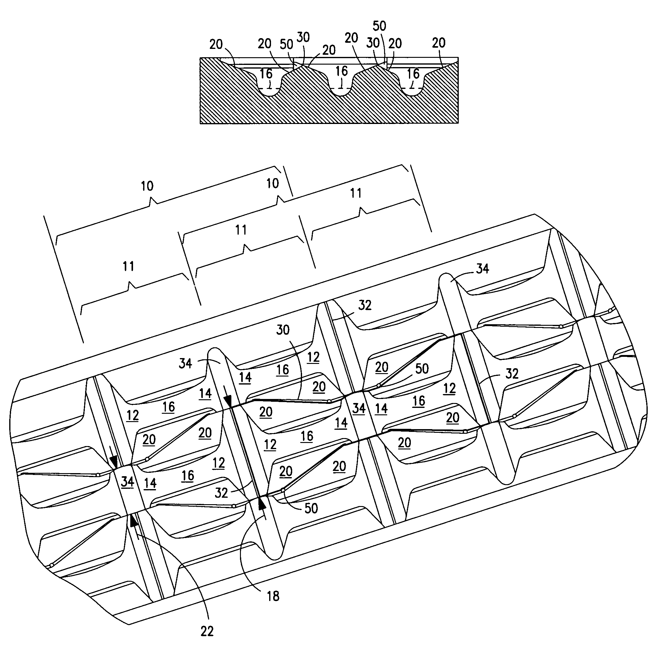
[0027]An exemplary embodiment of a surgical stapler anvil with nesting pockets will now be described with reference to FIGS. 6–12. FIG. 12 illustrates an exemplary surgical stapler anvil 40 configured for use in a surgical stapler which simultaneously cuts tissue while applying three staggered rows of surgical staples through tissue along either side of the incision. The pockets 10 in each row 42 are longitudinally offset from the pockets in an adjacent row such that the leg-receiving portions 12 of the pockets in one row are laterally adjacent to the leg-clinching portions 14 of the pockets in an adjacent row.

[0028]FIGS. 6 and 11 are enlarged plan and perspective views, respectively, of a surgical stapler anvil with nested pockets 10 according the aspects of the present invention. Each pocket 10 includes two mirror image leg-forming cups 11. Each leg-forming cup 11 is defined by a concave arcuate clinching surface 16 extending from a descending leg-receiving portion 12 to an ascend...


PUM

PropertyMeasurementUnit
Fractionaaaaaaaaaa
Angleaaaaaaaaaa
Angleaaaaaaaaaa

Abstract

A surgical stapler anvil provides an expanded leg-receiving target area for a staple forming pocket in a compact staggered array by narrowing the lateral width of the leg-clinching portion of a laterally adjacent pocket. Advantageously, the lateral spacing between adjacent rows of staple forming pockets can remain small, while the leg-receiving target area for laterally adjacent rows of pockets is significantly expanded. The staple forming pockets include two mirror image leg-forming cups. The cups are longitudinally aligned with their respective ascending leg clinching portions adjoining in the center of the pocket. Laterally spaced guide surfaces extend upwardly and outwardly from the clinching surface at the bottom of the cup to define an expanded leg-receiving target area at the distal ends of the pocket. Substantially planar laterally outward portions of the guide surface intersect with the guide surface of a laterally adjacent pocket to form a non-linear ridge.

Description

BACKGROUND OF THE INVENTION[0001]1. Field of the Invention[0002]The invention relates to surgical staplers, and more particularly to anvils for use in surgical staplers of the type in which one or more staples are driven through body tissue and against an anvil to form and clinch the staple legs and thereby secure the tissue.[0003]2. Description of the Related Art[0004]Surgical staplers having a wide variety of configurations are known. Generally, the tissue to be secured is positioned between a staple holding assembly and an opposing anvil assembly. One or more generally U-shaped staples are driven from the staple holding assembly, through the tissue, and against the anvil to bend the ends of the staple legs back toward the base of the staple. The formed and clinched staple secures the tissue. Many surgical staplers include staple holding assemblies and anvils configured to drive and form one or more rows of closely spaced staples. In staplers of this general type, it is important ...

Claims


Application Information

Patent Timeline
IPC IPC(8): A61B17/10A61B17/03A61B17/04B21J13/00B21D13/02
CPCB21D13/02A61B2017/07264A61B17/07207A61B2017/00526
Inventor DWORAK, BRUCE E.DWORAK, FRANK W.
Owner DWORAK FR W
Why Eureka
Try Eureka