
Protective device for a hand machine tool

a protection device and power tool technology, applied in the direction of metal sawing devices, manufacturing tools, metal-working machine components, etc., can solve the problems of insufficient dust removal, limited vacuum effect of sanding/grinding dust removal, etc., and achieve the effect of light weight and weight-saving fashion, particularly effective sanding/grinding dust removal

Inactive Publication Date: 2005-10-11
ROBERT BOSCH GMBH
View PDF24 Cites 12 Cited by
  • Summary
  • Abstract
  • Description
  • Claims
  • Application Information

AI Technical Summary

Benefits of technology

[0005]With a guard device of this type, a tool of a hand power tool, in particular a sanding / grinding hand power tool, can be enclosed by the wheel guard completely or to a predetermined extent, and, in fact, independent of the tool position relative to a work piece. As a result of this, an operator is protected to a large extent from particles that are removed from a work piece by the tool, i.e., sanding / grinding dust in particular. Additionally, sanding / grinding dust removal can be managed particularly effectively and, in most cases, neither an internal ventilator nor an external vacuum cleaner is required to remove dust. Due to the fact that the wheel guard is mounted in a fashion that allows it to move relative to the fastening device, the wheel guard is also mounted in a fashion that allows it to move relative to the tool position. As a result, the wheel guard can always lie on the work piece while the hand power tool is being operated, regardless of how far the tool enters the work piece. The guide means, which are interconnected with the wheel guard in torsion-resistant fashion, thereby guides the wheel guard along the work piece, by way of which it is ensured that the wheel guard bears against the work piece during operation without being able to tilt relative to the guide means. The wheel guard can therefore be held in a position that is constant relative to the surface of the work piece, independent of the depth of penetration of the tool in the work piece. Particles can therefore effectively be prevented from escaping from between the wheel guard and the surface of the work piece.
[0006]The invention is capable of being used particularly advantageously with a wheel guard for an angle grinder, since an angle grinder is used in mobile fashion and in various positions, e.g., in an overhead position. When the tool is completely enclosed or enclosed to a predetermined extent by the wheel guard, the operator is protected to a large extent from sanding / grinding dust.
[0007]The wheel guard encloses the tool in essential regions and, in particular, at least partially in the radial direction. In the case of a disc-shaped, rotating tool, at least one segment of the arc of the periphery of the tool is completely enclosed in the radial direction. Particles of the work piece being worked thrown off by the tool, such as sanding / grinding dust, are therefore captured by the wheel guard in the region in which it encloses the tool in the radial direction. Advantageously, the wheel guard encloses at least 120°, in particular at least 180° of the periphery of the tool, in order to capture as much dust as possible.
[0008]In an advantageous embodiment of the invention, the guide means comprise at least one sliding shoe. The wheel guard can be guided safely on the work piece on a sliding shoe that extends advantageously in the working direction of the tool. When the sliding shoe is designed with a flat bearing surface or bearing edge, the wheel guard is guided particularly safely over a flat work piece. By minimizing the guide means on a glide shoe that is seated tightly on the wheel guard, the wheel guard can be produced in a particularly lightweight and weight-saving fashion.
[0009]A particularly simple mounting of the wheel guard in a fashion that allows it to move relative to the fastening device is obtained by mounting the wheel guard in a fashion that allows it to swivel relative to the fastening device. The two elements can be interconnected at one center of rotation.
[0010]A particularly good level of sanding / grinding dust removal can be achieved when the wheel guard—in a state in which it lies on a flat work piece in the operating position—is provided to enclose the tool together with the work piece to an extent that does not depend on the depth of penetration of the tool in the work piece. The work piece can be enclosed entirely or to a predetermined extent, so that, when the tool is pulled out of the work piece, for example, no dust or no additional dust leaves the wheel guard and enters the surroundings.
[0010]A particularly good level of sanding / grinding dust removal can be achieved when the wheel guard—in a state in which it lies on a flat work piece in the operating position—is provided to enclose the tool together with the work piece to an extent that does not depend on the depth of penetration of the tool in the work piece. The work piece can be enclosed entirely or to a predetermined extent, so that, when the tool is pulled out of the work piece, for example, no dust or no additional dust leaves the wheel guard and enters the surroundings.
[0010]A particularly good level of sanding / grinding dust removal can be achieved when the wheel guard—in a state in which it lies on a flat work piece in the operating position—is provided to enclose the tool together with the work piece to an extent that does not depend on the depth of penetration of the tool in the work piece. The work piece can be enclosed entirely or to a predetermined extent, so that, when the tool is pulled out of the work piece, for example, no dust or no additional dust leaves the wheel guard and enters the surroundings.
[0013]A guard device, the wheel guard of which encloses the tool completely in the axial direction in the idle position, ensures a high level of work safety: an operator is protected effectively against injury caused by the tool. This also applies for a guard device, in the case of which the tool retracts completely into the wheel guard when it exits the work piece. Additionally, such a guard device ensures good protection against the release of sanding / grinding dust or particles. The dust rotating with the tool is drawn into the wheel guard along with the tool retracting into the wheel guard.
[0014]The wheel guard advantageously encloses two units that are movable relative to each other that, in mutual interplay, comprise an operating position and a tool replacement position, whereby at least one of the units, in the tool replacement position, exposes the tool in the axial direction to an extent that allows a tool to be replaced. With such an embodiment of the wheel guard, easy tool replacement is possible despite the fact that the tool is largely enclosed in the idle position. A design for this that is particularly simple is obtained by the fact that the two units are capable of being swiveled independently of each other around a common center of rotation relative to the fastening device. The two units are connected to the fastening device with a rivet or screw, for example. One of the units is a pivoted cover plate, for example. The arrangement of the pivoted cover plate to cover the axial side of the sanding disc / grinding wheel improves the work safety with the hand power tool and prevents sanding / grinding dust from escaping from the side, which makes it possible to replace the tool more quickly by swiveling the pivoted cover plate around a center of rotation. The pivoted cover plate can be closed particularly reliably and it is easy to open by means of the positive fastening system of the pivoted cover plate with lobes and snap-in tongues that snap in place together.
[0015]A further advantage is achieved in that the wheel guard comprises a window that allows an operator to see the tool and, in particular, on the side of the tool closest to a work piece. This makes it possible to control the position of the tool in the work piece particularly easily and effectively.
[0016]Advantageously, the wheel guard comprises an observation slit. It can be formed by means of an opening in the wheel guard, for example, or by means of a slant in a part of the wheel guard. The observation slit oriented toward the narrow side of the sanding disc / grinding wheel ensures a more controlled handling of the angle grinder with the wheel guard, mainly for exact placement of the sanding disc / grinding wheel in mortar joints. Visual control of the tool is particularly enhanced by means of the window in combination with an observation slit. The air-intake opening can be used as an observation slit. The air drawn in through the observation slit causes turbulence that essentially keeps the window free from dust. When the dust is removed from the opposite side of the window, e.g., by a dust removal tube located there, the air turbulence keeps the window essentially free from dust.
[0013]A guard device, the wheel guard of which encloses the tool completely in the axial direction in the idle position, ensures a high level of work safety: an operator is protected effectively against injury caused by the tool. This also applies for a guard device, in the case of which the tool retracts completely into the wheel guard when it exits the work piece. Additionally, such a guard device ensures good protection against the release of sanding / grinding dust or particles. The dust rotating with the tool is drawn into the wheel guard along with the tool retracting into the wheel guard.

Problems solved by technology

Guard devices for hand power tools, in particular for angle grinders, are known, the wheel guards of which offer a certain level of protection during sanding / grinding work, but which do not support a sufficient level of dust removal.
The removal of sanding / grinding dust using vacuum is therefore only slightly effective, despite the powerful external vacuum cleaners that are typically used

Method used


Image

  • Protective device for a hand machine tool
  • Protective device for a hand machine tool
  • Protective device for a hand machine tool

Examples


Embodiment Construction

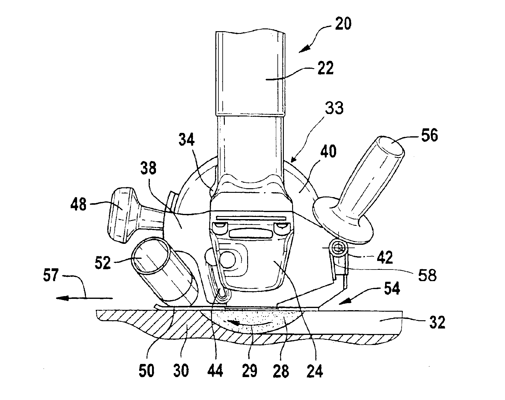
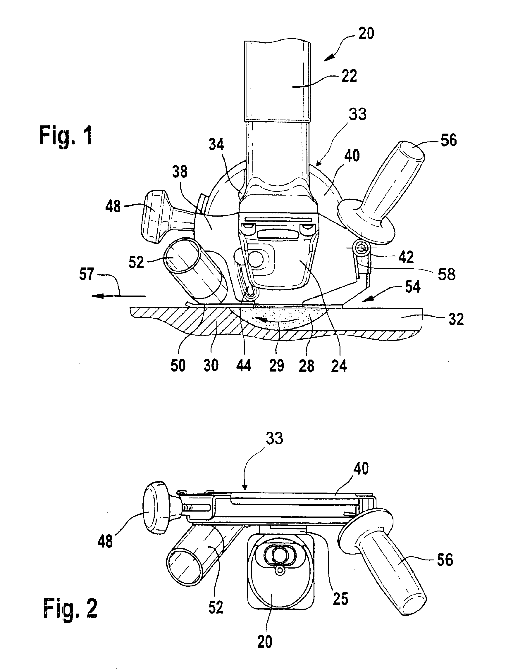
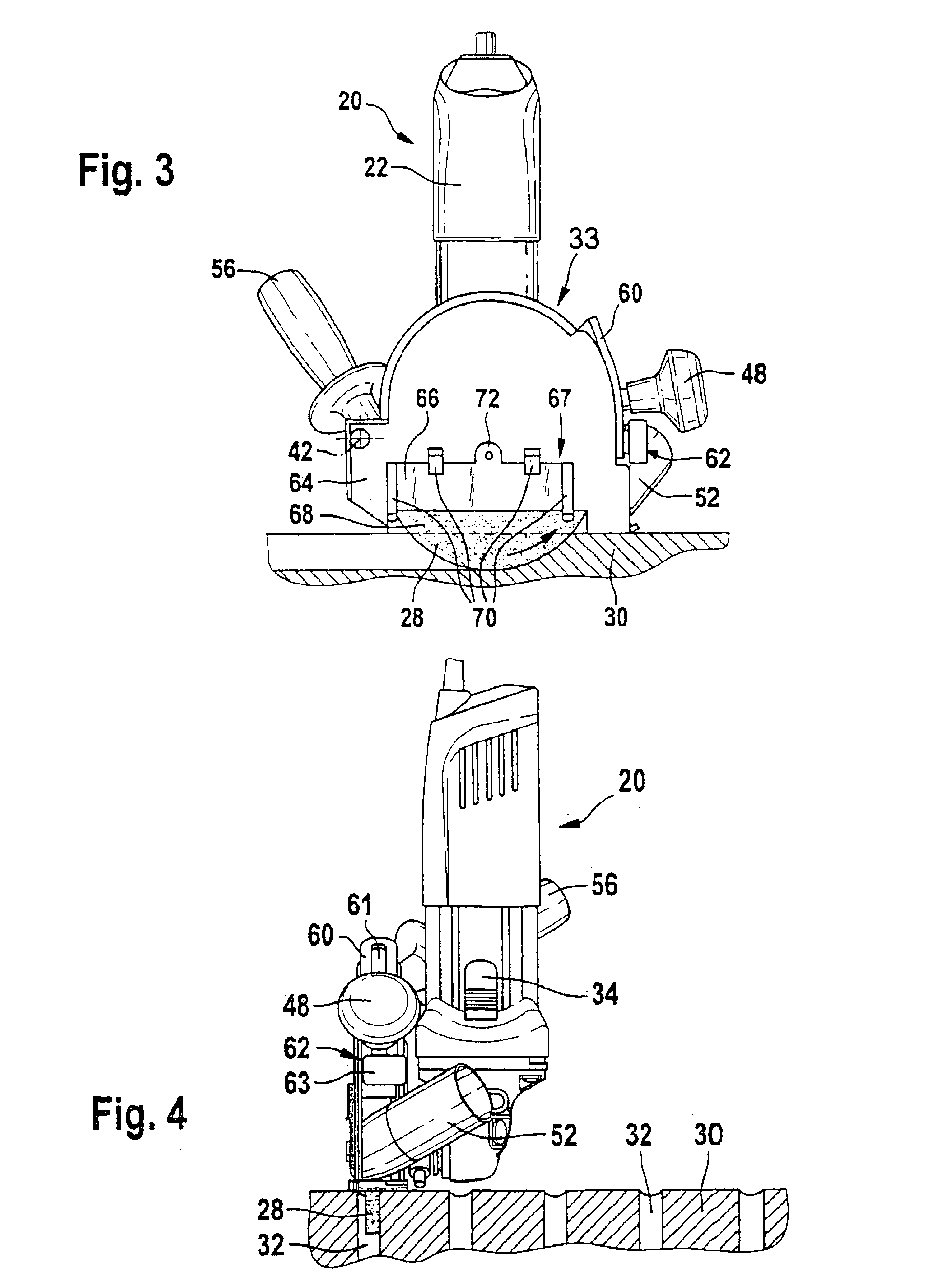
[0041]FIG. 1 is the side view of an angle grinder 20, the motor housing 22 of which extends substantially upward at a right angle and contains a not-shown motor.

[0042]As viewed downward at a right angle, a gearbox housing 24 adjoins the motor housing 22, the driven shaft 26 (FIG. 13) of which said gearbox housing extends at a right angle to the plane of the drawing and has a tool mounted on its exposed end. The tool is a sanding disc / grinding wheel 28. It rotates in the direction of rotation 29 in the clockwise direction and plunges into a work piece 30, in which it cuts a groove 32 coming from the right.

[0043]As shown on the left side, a sliding button 34 of an on-and-off switch is mounted on the motor housing 22.

[0044]A guard device 33 is mounted on the angle grinder 20. It comprises a fastening device and a wheel guard 40. The fastening device is designed as a swiveling arm 38. The swiveling arm 38 is mounted via a well-fitting mounting opening 36 (FIG. 18) on a cylindrically-sha...


PUM

PropertyMeasurementUnit
angleaaaaaaaaaa
penetration depthaaaaaaaaaa
sizeaaaaaaaaaa

Abstract

A guard device for a hand power tool, in the form of a sanding / grinding hand power tool, has a wheel guard enclosing at least part of a rotating tool in a radial direction; a guide for guiding the wheel guard along a work piece, and comprising a fastening device for mounting the wheel guard on the hand power tool, wherein the guide is joined with the wheel guard in torsion-resistant fashion, and the wheel guard is mounted in a fashion that allows it to move relative to the fastening device; and a depth-of-cut stop limiting the relative movement of the wheel guard and fastening device, and being lockable in position with positive engagement in preselected stepped positions.

Description

BACKGROUND OF THE INVENTION[0001]The invention is based on a guard device for a hand power tool, in particular for a sanding / grinding hand power tool, according to the preamble of claim 1.[0002]Guard devices for hand power tools, in particular for angle grinders, are known, the wheel guards of which offer a certain level of protection during sanding / grinding work, but which do not support a sufficient level of dust removal. This is due to the fact that, during operation and in the idle position, the wheel guard covers only part of the side of the tool and, in particular, a sanding disc / grinding wheel of the hand power tool. The removal of sanding / grinding dust using vacuum is therefore only slightly effective, despite the powerful external vacuum cleaners that are typically usedADVANTAGES OF THE INVENTION[0003]The invention is based on a guard device for a hand power tool, in particular for a sanding / grinding hand power tool, comprising a wheel guard that is provided to enclose at l...

Claims


Application Information

Patent Timeline
Patent Type & Authority Patents(United States)
IPC IPC(8): B23Q11/00B24B23/02B24B23/00B24B55/05B24B55/00
CPCB23Q11/0046B24B23/028B24B55/052Y10T83/7734
Inventor WENDT, DIETERSCHANBACHER, JUERGENSCHANBACHER, HEIDEMARIEVOIGT, MIKEKLEIDER, ALBERTSCHADOW, JOACHIMNEEF, KURT
Owner ROBERT BOSCH GMBH
Learn More