
High resolution multi-lens imaging device

a multi-lens, high-resolution technology, applied in the field of imaging, can solve the problems of troublesome handling of images and accompanying instruments, obviating the use of multi-lens cameras, and complicated special rectifiers and plotting instruments to restore image geometry, etc., to achieve the effect of better focusing

Inactive Publication Date: 2005-10-11
UNIV OF FLORIDA RES FOUNDATION INC +2
View PDF5 Cites 40 Cited by
  • Summary
  • Abstract
  • Description
  • Claims
  • Application Information

AI Technical Summary

Benefits of technology

[0007]An imaging system allowing electronic changes from large to small field of view, with a concomitant change from a low resolution to a high resolution is described. The additional use of photon sieves for lenses can provide better focusing in the high resolution configuration of a small, light weight package (although the present invention is not necessarily limited to small and light weight packages).

Problems solved by technology

Several Aerial Cameras with multiple lenses were built, but complicated special rectifiers and plotting instruments were developed to restore the image geometry.
Handling of the image and the accompanying instruments was troublesome and eventually obviated the use of multi-lens cameras by the development of new single-lens cameras with larger negative formats.

Method used


Image

  • High resolution multi-lens imaging device
  • High resolution multi-lens imaging device
  • High resolution multi-lens imaging device

Examples


Embodiment Construction

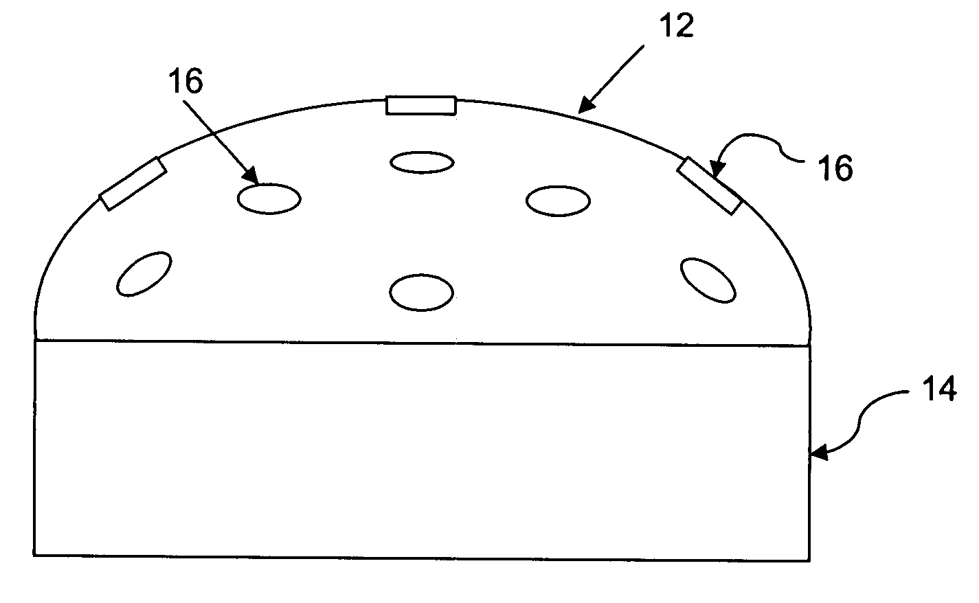
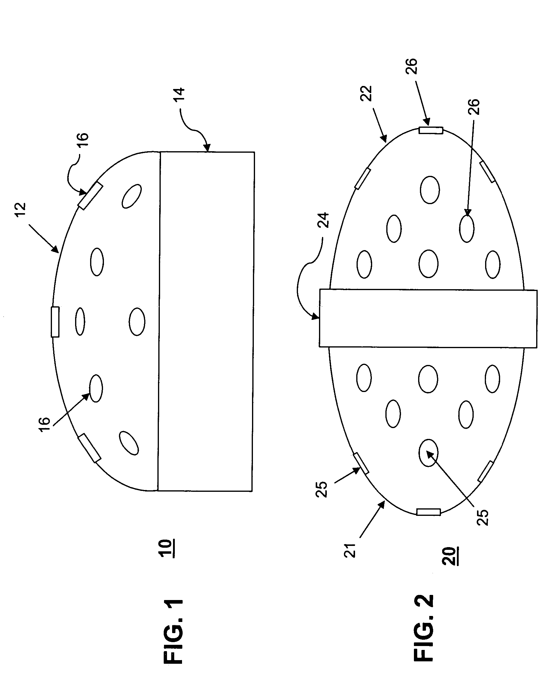
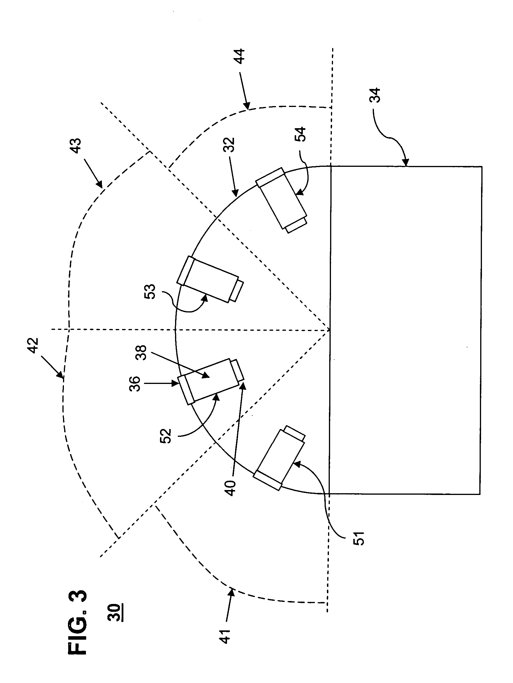
[0016]Referring to FIG. 1, a camera 10 is shown having a plurality of lenses 16 on a hemispherical support structure 12. Each of the plurality of lenses can have an associated optical detector as will be shown in FIG. 3. Each of the images from the plurality of lenses and corresponding detectors can be processed by electronics and / or software residing on substrate 14. The camera 10 can provide a 180 degree field of view. Another camera 20 shown in FIG. 2 can provide a 360 degree field of view. The camera 20 can include a first substantially hemispherical (or egg-shaped or elliptical) support structure 21 having a plurality of lenses 25 and a second support structure 22 having a plurality of lenses 26. As with camera 10, camera 20 can also have a plurality of corresponding optical detectors (not shown). Each of the images from the plurality of lenses and corresponding detectors can be processed by electronics and / or software residing on substrate 24. Note that the lenses shown in the...


PUM


Abstract

An imaging device (30) can include a plurality of lenses (51, 52, 53, 54) mounted on a multi-dimensional support structure (32), a plurality of optical detectors (40) corresponding to the plurality of lenses for capturing an optical signal from at least two lenses among the plurality of lenses, and a processor (34) for combining the optical signal from at least two lenses to form an image and electronically controlling the field of view and a resolution of the image. The plurality of lenses each can include an array of sub-wavelength apertures or a plurality of photon sieve lenses (36).

Description

STATEMENT REGARDING FEDERALLY SPONSORED RESEARCH OR DEVELOPMENT[0001]The United States Government has rights to this invention pursuant to Grant No. N000140310418 from the Office of Naval Research.BACKGROUND OF THE INVENTION[0002]1. Technical Field[0003]This invention relates to the field of imaging and more particularly to imaging using multiple lenses.[0004]2. Description of the Related Art[0005]Digital Modular Cameras (DMC) by Z / I Imaging (a joint venture between Carl Zeiss and Intergraph) currently provide accurate high resolution images using multi-lens cameras and a corresponding matrix of charge coupled devices (CCD). The DMC comprises a variable number of synchronously operating CCD-matrix based cameras that can be mounted together in different configurations, depending on the application. The multi-camera approach allows the combination of high panchromatic resolution with multi-spectral capability. The idea to enlarge the field of view by combining several lens systems is ...

Claims


Application Information

Patent Timeline
Patent Type & Authority Patents(United States)
IPC IPC(8): G02B13/06H04N5/225
CPCG02B13/06H04N5/2251H04N5/2254H04N5/23238H04N23/55H04N23/698
Inventor HOLLOWAY, PAUL H.DAVIDSON, MARK R.SHENDEROVA, OLGA ALEXANDERMCGUIRE, GARY E.TANNER, DAVID B.HEBARD, ARTHUR
Owner UNIV OF FLORIDA RES FOUNDATION INC
Learn More