Magnetic recording head including spatially-pumped spin wave mode writer

a technology of spatial pumping and writing head, applied in the field of magnetic recording head, can solve the problems of distorted write field shape in the media, and inability to achieve longitudinal recording

Inactive Publication Date: 2005-10-11
SEAGATE TECH LLC
View PDF26 Cites 35 Cited by
  • Summary
  • Abstract
  • Description
  • Claims
  • Application Information

AI Technical Summary

Problems solved by technology

The recording densities possible with longitudinal recording are believed to be limited to approximately 50 to 100 Gbit / inch2 because, at higher recording densities, superparamagnetic effects result in magnetic instabilities within the magnetic storage medium.
The presence of underdamped FMR oscillations in the write field may cause distorted write field shapes in the media.
Furthermore, the flux transmission velocity through the write head yoke is not necessarily equal to the FMR-limited switching speed.
Therefore, at high data rates, conventional designs may be limited by the dispersion characteristics of the mode propagating through the yokes to the pole tips.

Method used


Image

  • Magnetic recording head including spatially-pumped spin wave mode writer
  • Magnetic recording head including spatially-pumped spin wave mode writer
  • Magnetic recording head including spatially-pumped spin wave mode writer

Examples


Embodiment Construction

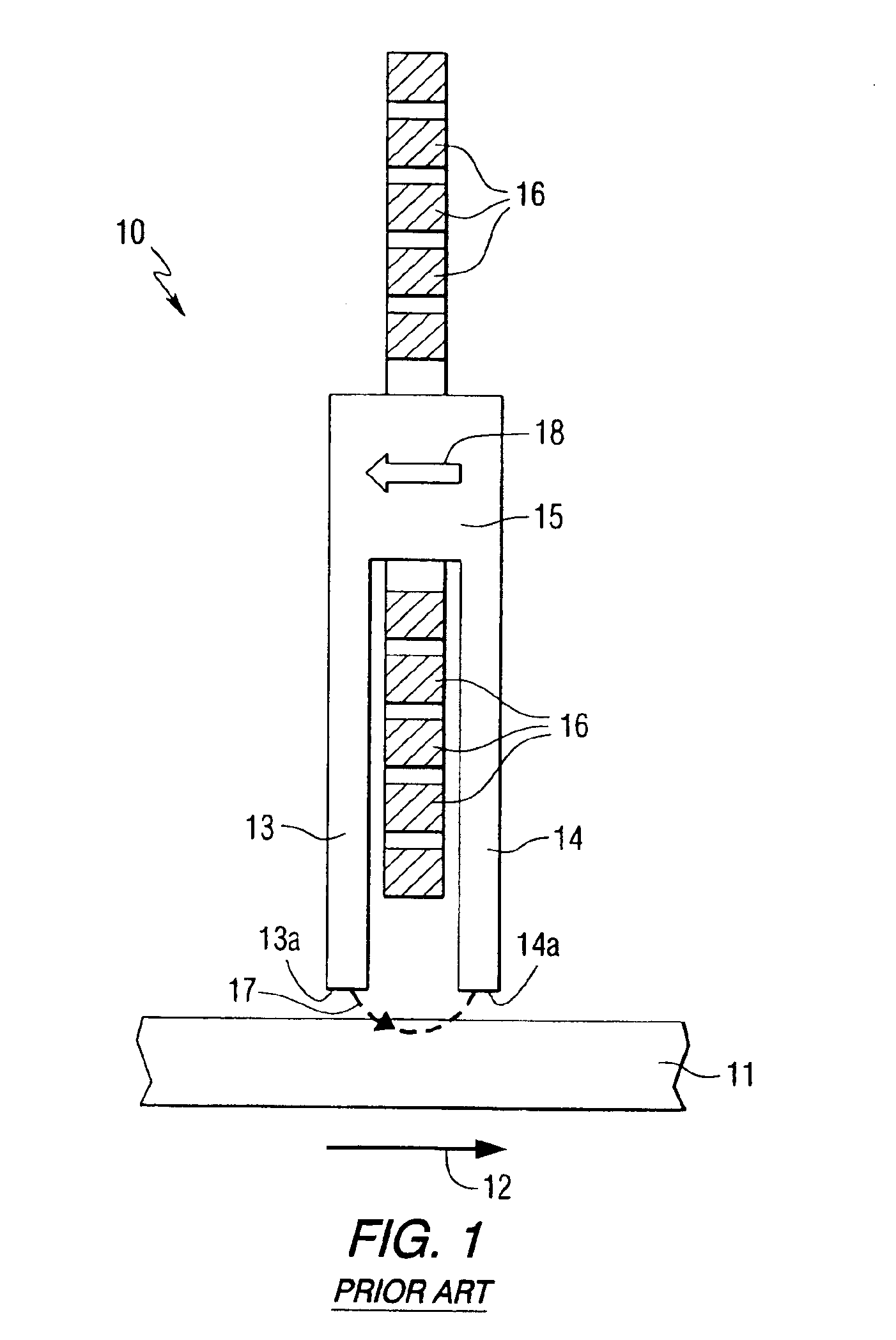
[0025]FIG. 1 illustrates a conventional longitudinal writer 10 positioned over a magnetic recording medium 11. During recording operations, the recording medium 11, such as a magnetic disc, moves in the direction of the arrow 12 in relation to the writer 10. The writer 10 includes two write poles 13 and 14 connected by a yoke 15. The write poles 13 and 14 have write pole tips 13a and 14a located at the air bearing surface of the writer 10. A multiple-turn coil 16 surrounds the yoke 15. The coil 16 is located relatively far away from the write pole tips 13a and 14a and the air bearing surface of the writer 10. When current is applied through the coil 16, a writing field 17 is generated from the pole tips 13a and 14a. With the conventional arrangement shown in FIG. 1, the driving field 18 is predominantly located at the back yoke 15. The writing field 17 that emerges from the write pole tips 13a and 14a relies on flux transmission from the yoke 15 to the pole tips 13a and 14a. The yok...


PUM

PropertyMeasurementUnit
frequencyaaaaaaaaaa
frequencyaaaaaaaaaa
magnetization angleaaaaaaaaaa

Abstract

The present invention provides magnetic recording heads which utilize higher order excitations of dynamic magnetization to increase frequency without the necessity of biasing the write yoke. In accordance with the present invention, the size and placement of current-carrying microstrip waveguide(s) and write pole(s) are controlled in order to generate spin wave write modes. During writing operations, the magnetization is driven into higher order spatial spin wave modes.

Description

CROSS REFERENCE TO RELATED APPLICATION[0001]This application claims the benefit of U.S. Provisional Patent Application Ser. No. 60 / 313,920 filed Aug. 21, 2001.FIELD OF THE INVENTION[0002]The present invention relates to magnetic recording heads, and more particularly relates to magnetic write heads with microstrip waveguides which control write pole magnetization.BACKGROUND INFORMATION[0003]Longitudinal and perpendicular recording heads for use with a magnetic storage medium are generally known. Longitudinal recording heads utilize a pair of opposing write poles with their tips in close proximity to each other at the bottom surface of the recording head. The two poles are connected at the top by a yoke, which may be made of a ferromagnetic material similar to that used for the poles. In conventional designs, a coil having multiple turns surrounds the yoke in close proximity to the two opposing poles. When a current is passed through the coil, magnetic flux is induced in the yoke, wh...

Claims


Application Information

Patent Timeline
Patent Type & Authority Patents(United States)
IPC IPC(8): G11B5/127G11B5/17G11B5/00G11B5/31
CPCG11B5/127G11B5/1278G11B5/17G11B5/31G11B2005/0002G11B2005/0005G11B2005/0029
Inventor CRAWFORD, THOMAS MCLENDONCOVINGTON, MARK WILLIAMPARKER, GREGORY JOHN
Owner SEAGATE TECH LLC
Why Eureka
Try Eureka