Active heating of thermally insulated flowlines

a flowline and active heating technology, applied in the direction of fluid removal, insulation, borehole/well accessories, etc., can solve the problem that conventional pipe-in-pipe systems may not be able to provide sufficient thermal insulation, and achieve the effect of relatively trouble-free production, cost-effective and reliable, and cost-effectiv

Inactive Publication Date: 2005-10-18
SUBSEA 7 US
View PDF20 Cites 34 Cited by
  • Summary
  • Abstract
  • Description
  • Claims
  • Application Information

AI Technical Summary

Benefits of technology

[0011]It is thus proposed to supplement the hydrocarbon-temperature-sustaining thermal insulation properties of pipe-in-pipe systems with an additional active heating system disposed within the outer carrier pipe. The present invention enables the active heating to be provided by a hot water system located within the outer carrier pipe, with the water provided by the processing facilities or a via a water heating system located at the well end of the flowline and energised by power from a platform or other installation that is the flowline destination (or a flowline waystation). This will allow the pipe-in-pipe concept to be used in more aggressive hydrocarbon fluid conditions by enabling the production and relatively trouble-free transport of a wider range of hydrocarbon fluids than could be reliably carried in unheated flowlines. The pipe-in-pipe concept also provides a method of keeping the fluids warm during shut-in conditions, and is expected to prove more cost effective and reliable than electrical active heating systems which h

Problems solved by technology

Under these shut-in conditions, even conventional pipe-in-pipe systems may not be able to provide sufficient thermal insulation to maint

Method used


Image

  • Active heating of thermally insulated flowlines
  • Active heating of thermally insulated flowlines
  • Active heating of thermally insulated flowlines

Examples


Embodiment Construction

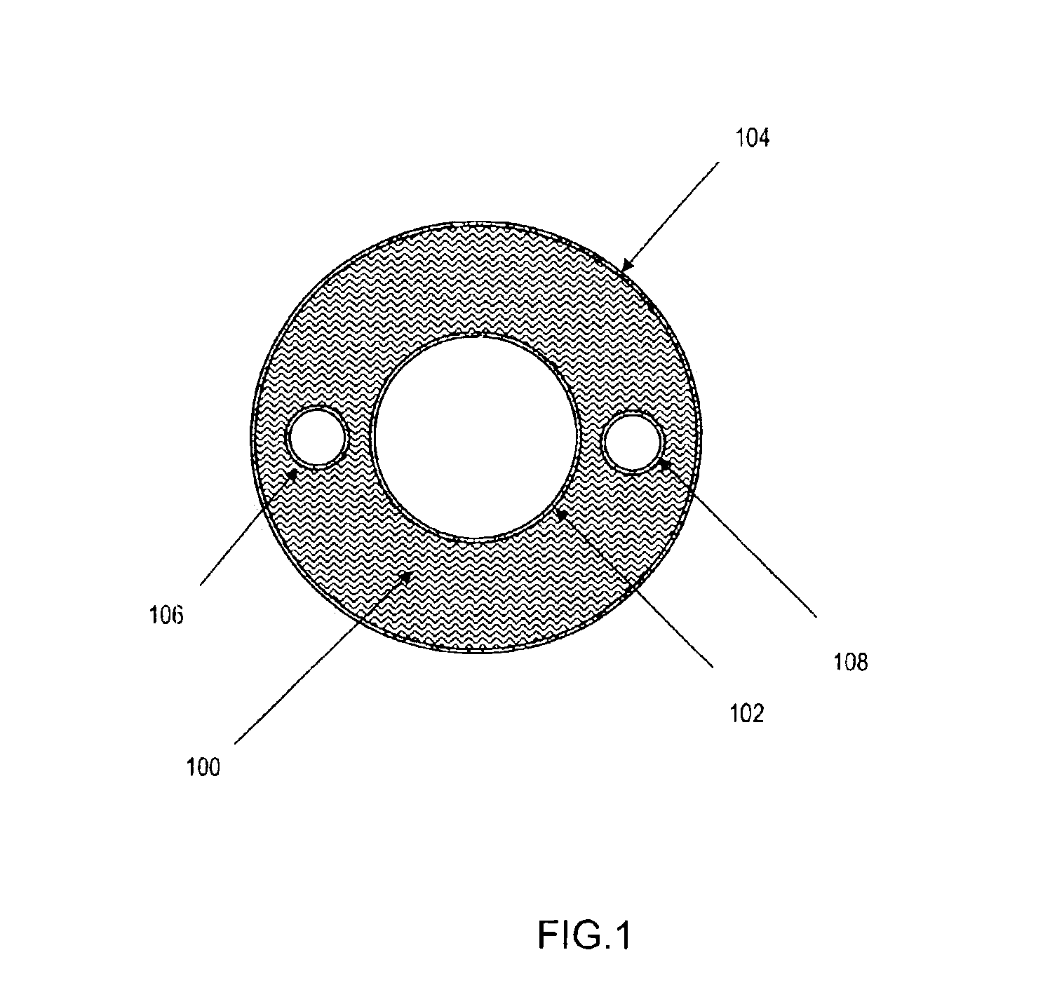
[0017]Referring first to FIG. 1, this shows the schematic transverse cross-section of a pipe-in-pipe (“p-i-p”) thermally insulated hydrocarbon-transporting flowline wherein hot hydrocarbon liquids (or hydrocarbon liquid / gas mixtures) are transported along the inner pipe, and are thermally insulated by an annular blanket of thermally insulating material 100 substantially filling the annulus between the inner hydrocarbon-transporting flowline pipe 102 and the concentric outer carrier pipe 104. A hot water input pipe 106 is located radially mid-way between the inner and outer pipes, and extends along the length of the pipe-in-pipe flowline. Diametrically opposite the hot water input pipe 108, a hot water return pipe is located radially mid-way between the inner and outer pipes, and extends along the length of the pipe-in-pipe flowline.

[0018]The pipe may be made in double walled sections or assembled from inner and outer pipe sections as described in co-pending applications of associate...


PUM


Abstract

Hydrocarbon liquids are transported from a subsea welihead to an above-surface hydrocarbon processing facility along a pipe-in-pipe flowline. The flowline is a pipe placed coaxially within an outer carrier pipe and the annulus between the pipes is filled with thermally insulating material. The hydrocarbon liquids have their temperature maintained above solidification/precipitation temperature by heat from an active heating system. Hot liquid, preferably hot water, is passed along the annulus, either along a single pipe or multiple pipes installed in the insulation-filled annulus, or along an inner annulus formed by a water pipe added concentrically around the hydrocarbon-transporting inner pipe, inside the outer insulation-filled annulus. The water or other suitable liquid can be heated in a heater at or adjacent the subsea wellhead, or by a water heater in the above-surface hydrocarbon processing facility.

Description

CROSS REFERENCE TO RELATED APPLICATION[0001]This application claims priority from U.S. Provisional Patent Application No. 60 / 385,243 filed in May 31, 2002. The entire disclosure of the provisional application is considered to be part of the disclosure of the accompanying application and is hereby incorporated by reference.[0002]This invention relates to active heating of thermally insulated flowlines, and relates more particularly to the active supply of heat to hydrocarbons in hydrocarbon-transporting flowlines of the pipe-in-pipe type.BACKGROUND OF THE INVENTION[0003]In the development and exploitation of submarine hydrocarbon reservoirs, subsea wells are commonly used to extract the hydrocarbon fluids which can then be transported through submarine flowlines to above-surface hydrocarbon processing facilities at sea or on land. Depending on the characteristics of the hydrocarbon fluids, it may be necessary to maintain the temperature of the hydrocarbon fluids being transported in ...

Claims


Application Information

Patent Timeline
IPC IPC(8): E21B43/00E21B36/00E21B43/01
CPCE21B36/005E21B43/01
Inventor BURSAUX, GABRIEL ANDRE
Owner SUBSEA 7 US
Why Eureka
Try Eureka