Industrial vehicle

Inactive Publication Date: 2005-10-18
TCM
View PDF8 Cites 18 Cited by
  • Summary
  • Abstract
  • Description
  • Claims
  • Application Information

AI Technical Summary

Benefits of technology

[0013]A third object of the invention is to provide an industrial vehicle in which an operator can easily attach and detach a document

Problems solved by technology

Conventionally, in fork lifts, operators sitting on a seat perform operations while running backward the fork lift in a backward-facing driving posture in many cases, but since the seat is fixed to face forward, during backward running the operators have to drive the fork lift in an unnatural posture with the upper part of their body twisted at nearly 180 degrees backward, which increases operators' fatigue and makes it difficult to secure the rear view.
In addition, when they get on and off from one of right and left sides of the seat, they get on and off with less ease.
On this occasion, the operator may operate the accelerator pedal

Method used


Image

  • Industrial vehicle
  • Industrial vehicle
  • Industrial vehicle

Examples


first embodiment

[0060]To begin with, the present invention will be described based on FIG. 1 to FIG. 11.

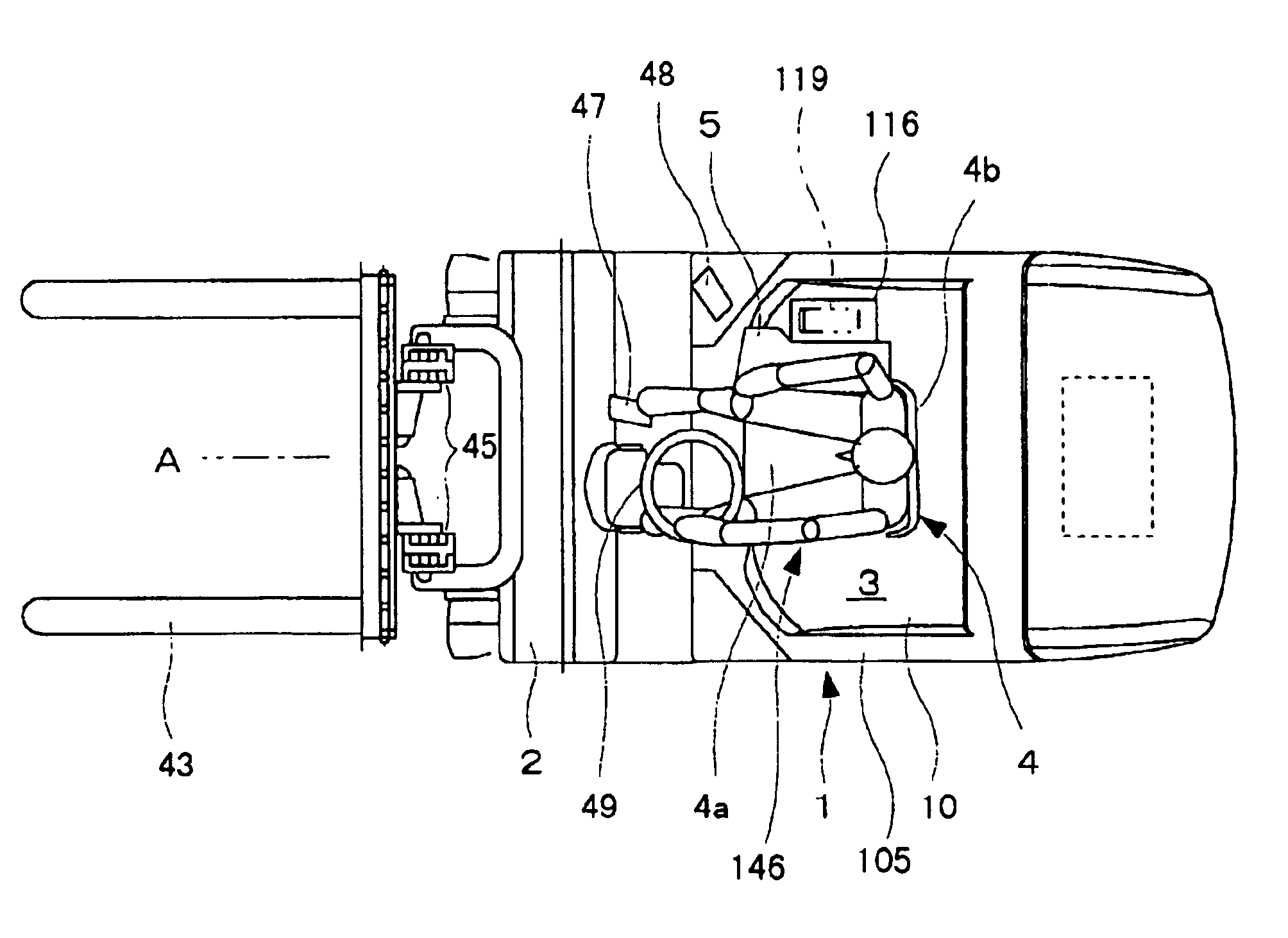
[0061]FIG. 9 is a plan view of a fork lift 1, an example of an industrial vehicle. A driver's room 3 of a vehicle body 2 is provided with a seat 4, a steering wheel 49 and the like. As shown in FIG. 8, an arm rest 5 where an operator sitting on the seat 4 places his or her elbow is provided at a right side of the above-described seat 4. The above-described seat 4 is constituted by a seating portion 4a and a backrest 4b.

[0062]As shown in FIG. 5 to FIG. 7, a lower frame 8 is provided at a lower part of the above-described seat 4, and the lower frame 8 is provided with a rotating shaft 9 in a cylindrical form projecting downward. A cylindrical fixed bearing member 11 is vertically provided on a floor 10 of the driver's room 3, and the above-described rotating shaft 9 is fitted into the fixed bearing member 11 from above to be horizontally rotatable. As a result, the above-described seat 4 is constr...

second embodiment

[0086]Next, the present invention will be described with reference to FIG. 9 to FIG. 21.

[0087]As shown in FIG. 9, the above-described main accelerator pedal 47 is provided to the right and in front of the seat 4 in the forward facing position A, and as shown in FIG. 10, the above-described auxiliary accelerator pedal 48 is provided to the right and in front of the seat 4 in the clockwise rotated position R. When the auxiliary accelerator pedal 48 is depressed, the above-described main accelerator pedal 47 is interlocked with the auxiliary accelerator pedal 48 via an interlock mechanism 55.

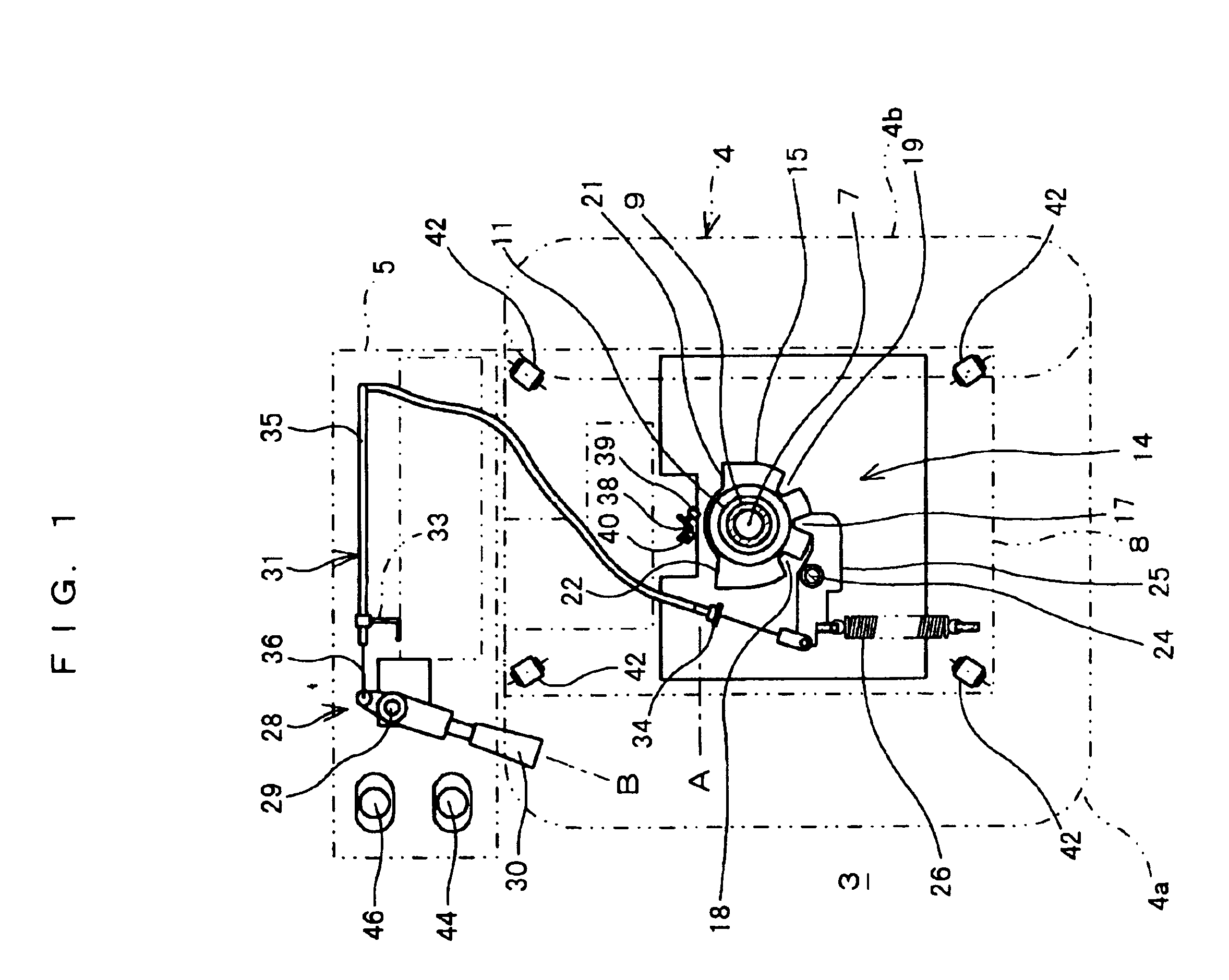
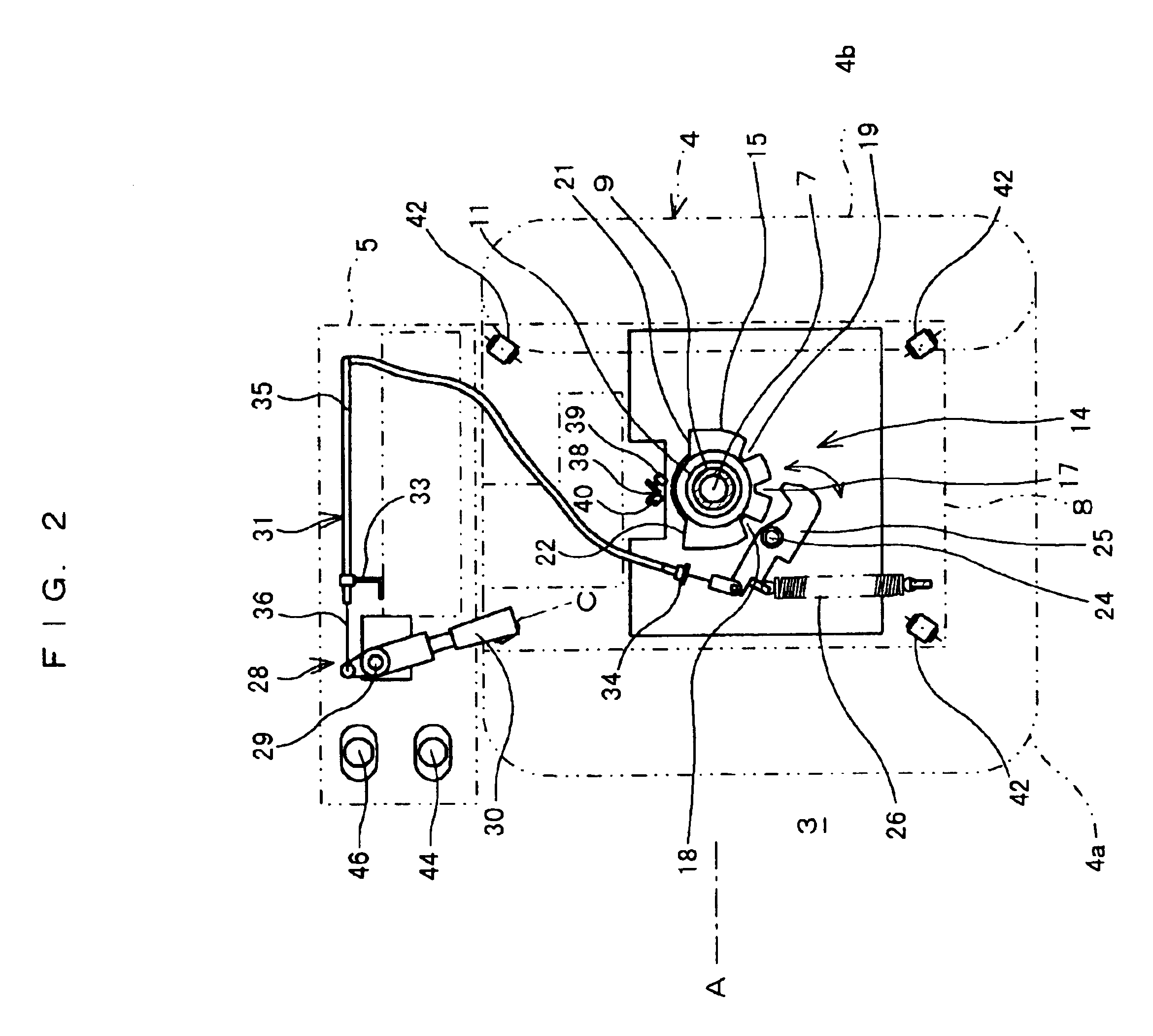
[0088]As shown in FIG. 12 and FIG. 13, the above-described interlock mechanism 55 is constituted by a main accelerator link 57 which can be rotated by depressing the main accelerator pedal 47 and returned to an original position by a main return spring 56, an auxiliary accelerator link 59 which can be rotated by depressing the auxiliary accelerator pedal 48 and returned to an original position by a...

third embodiment

[0102]In consideration of the above, a structure which makes it possible to reduce depressing force on operating each of the accelerator pedals 47 and 48 will be explained below based on FIG. 16 to FIG. 21 as the present invention.

[0103]As shown in FIG. 16, an interlock mechanism 77 interlocking with the throttle valve 67 is provided between the main accelerator pedal 47 and the auxiliary accelerator pedal 48.

[0104]The above-described interlock mechanism 77 is constituted by a main accelerator link 79 which can be rotated by depressing the main accelerator pedal 47 and returned to an original position by a main return spring 78, an auxiliary accelerator link 81 which can be rotated by depressing an auxiliary accelerator pedal 48 and returned to an original position by an auxiliary return spring 80, one and the second intermediate links 83 and 84 which can be rotated about the same axis 82 as the above-described main accelerator link 79, and a pull cable 85 (an example of an interloc...


PUM


Abstract

An industrial vehicle having a seat placed in a driver's room provided in a vehicle body to be rotatable at a predetermined angle in at least one of a clockwise direction and a counterclockwise direction with respect to a forward facing position, wherein the driver's room includes a main accelerator pedal at a position corresponding to the seat in the forward facing position and an auxiliary accelerator pedal at a position corresponding to the seat in a position rotated at a predetermined angle from the forward facing position and the main accelerator pedal is interlockable with the auxiliary accelerator pedal.

Description

CROSS REFERENCE TO RELATED APPLICATION[0001]This application is a division of U.S. application Ser. No. 10 / 182,475 filed Jul. 29, 2002 now abandoned which is a 371 of PCT / JP00 / 03890 filed Jun. 14, 2000 which claims priority from Japanese application nos. 200055071, filed Mar. 1, 2000; 200067883, filed Mar. 13, 2000; and 200069579, filed Mar. 14, 2000.TECHNICAL FIELD[0002]The present invention relates to an industrial vehicle running forward and backward, such as, for example, a fork lift.BACKGROUND ART[0003]Conventionally, in fork lifts, operators sitting on a seat perform operations while running backward the fork lift in a backward-facing driving posture in many cases, but since the seat is fixed to face forward, during backward running the operators have to drive the fork lift in an unnatural posture with the upper part of their body twisted at nearly 180 degrees backward, which increases operators' fatigue and makes it difficult to secure the rear view. In addition, when they ge...

Claims


Application Information

Patent Timeline
IPC IPC(8): A47C7/56A47C1/00A47C1/121A47C7/00A47C3/18A47C3/00B66F9/075
CPCA47C1/121A47C3/18A47C7/56B66F9/0759B60N2/146Y10T74/20534Y10T74/20213B60Y2200/15B66F9/07504
Inventor UEDA, JYUNOHE, NORIHIROKIKUCHI, EIICHI
Owner TCM
Why Eureka
Try Eureka